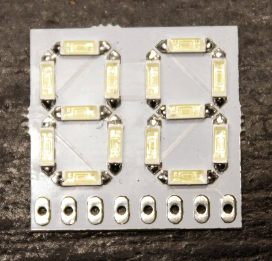
I received the very first order recently, and it won't be of much use...
We already know that the circuit is wrong because of the protection diode (which could also be a Zener but at this point, who cares ?).
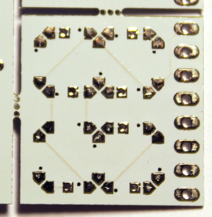
Now, it's time to examine the PCB of the first version and look at other problems.
The PCB did not get my "tented vias" and there are exposed signals under the LEDs.
I have put the vias under the LEDs because I didn't want visual distractions.
However the LEDs have heatsink pads that are electrically connected so short circuits will happen.
Even worse: the HASL treatment increases the height of the via and adding insulating Kapton will make the part unsolderable because the pads won't touch the contacts...
Fortunately, Rev.2 indirectly solved this problem because it's a single-sided PCB. No via.
The diameter of the connectors seems to be ok and standard pins can go through it.
I should try to solder a few LEDs, now...
20160902:
I soldered a few LEDs and it's not for beginners but it's not hard either. Just use very thing soldering wire, and apart from the problems with the vias etc., the layout and the footprints don't need to be modified. That's a relief :-)

 Yann Guidon / YGDES
Discussions
Become a Hackaday.io Member
Create an account to leave a comment. Already have an account? Log In.
If you need it for testing: I do have running (tested with ugly prototype) code for controlling it with a Atmel AVR controller.
Are you sure? yes | no
Don't hesitate to add the files to this project. I'm sure others (including @Dylan C. ) will find it useful :-)
Are you sure? yes | no