As the printer controls only supported bed pre-heating to 60C, the first thing to do was to see if the controller would support higher temperatures so I created a file with a single gcode in it:
M190 S110
This instructs the controller to heat the bed to 110C. I ran the file and the controller showed a set temperature of 110C. Unfortunately the bed heater was only powerful enough for the bed to reach around 75C but the results were encouraging. So, I decided to bond a second "slave" heater underneath the bed driven from a separate power supply, as the original PSU would not be able to supply the extra 7 to 8 amps required. The second heater would be controlled by a relay with the coil being driven from the original heater supply. That way both heaters would be controlled together. In my original experiments I used a relay but the clicking, as the PID controller set the temperature, was annoying so I changed to using a Mosfet instead.
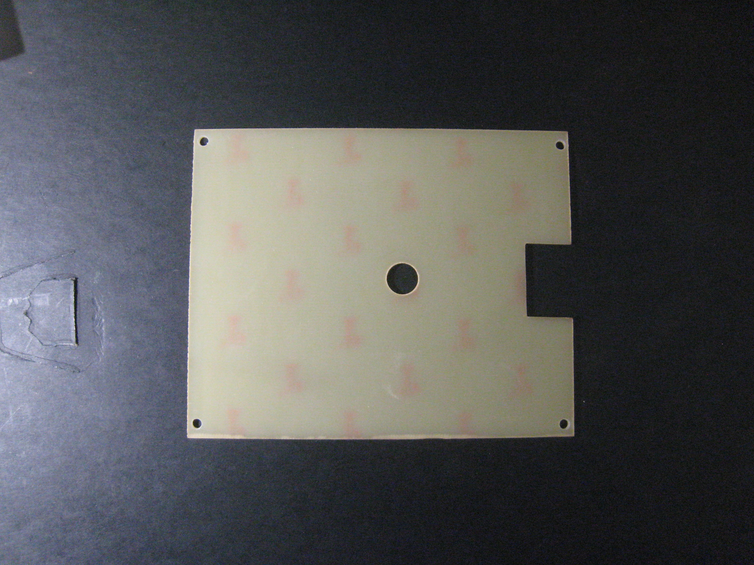
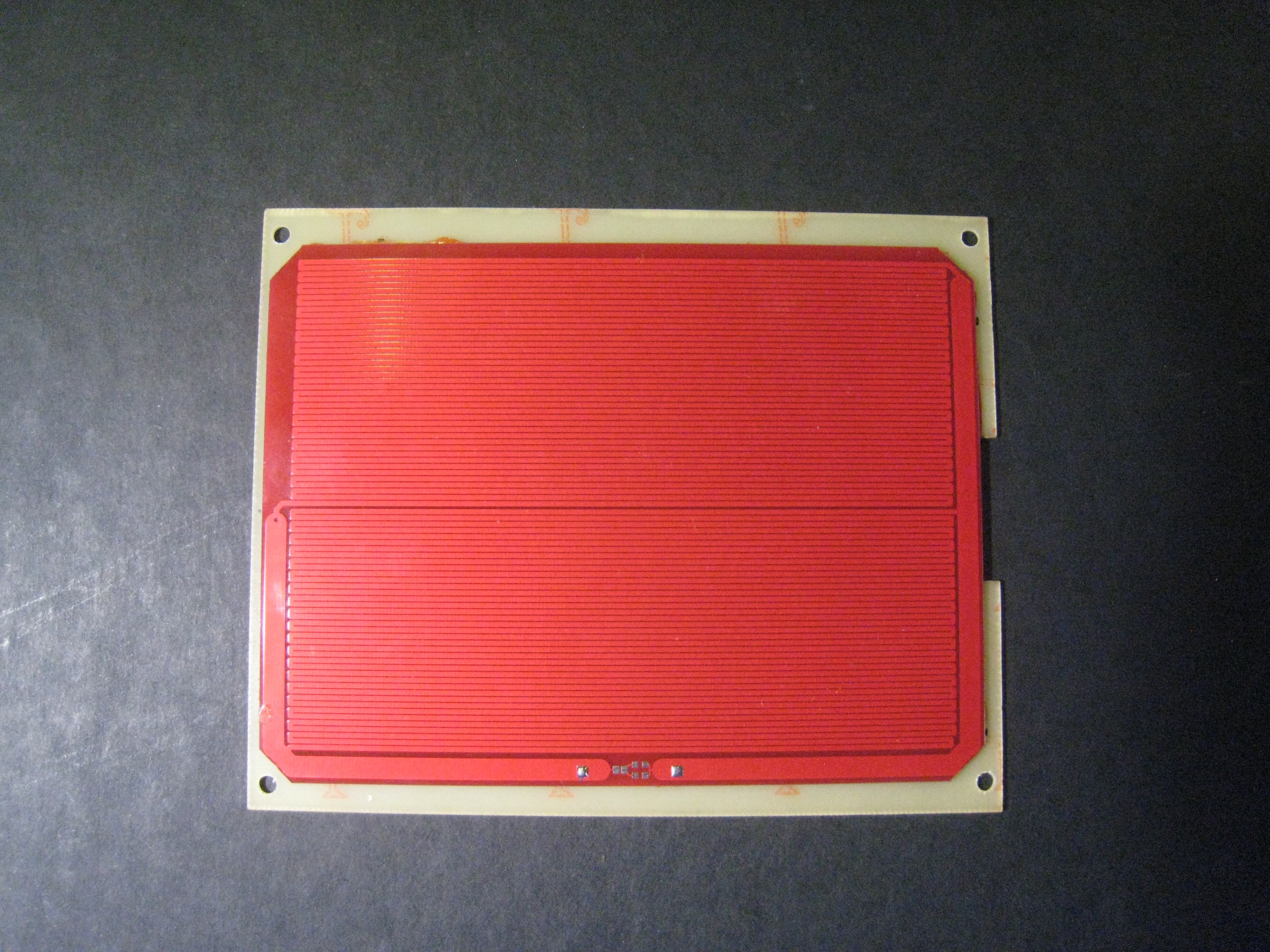
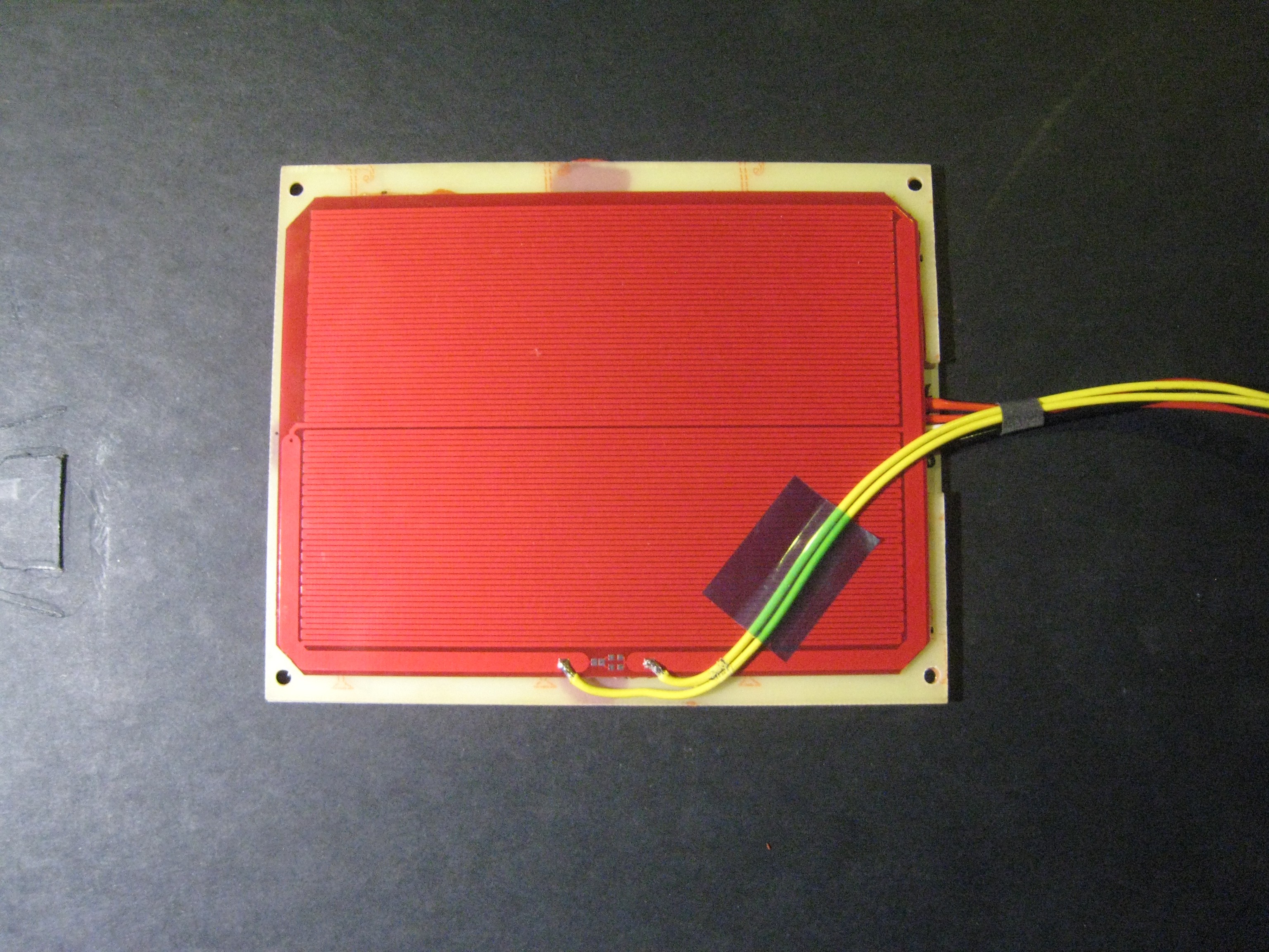
I found a 4.5" by 6" 12 volt heater on Ebay for $14.50. The next step was to attach it to the bed. The new heater is shown below.
 ---------- more ----------The new heater could not be attached directly to the bottom of the bed as the connecting wires and thermistor are raised from the bottom of the bed.
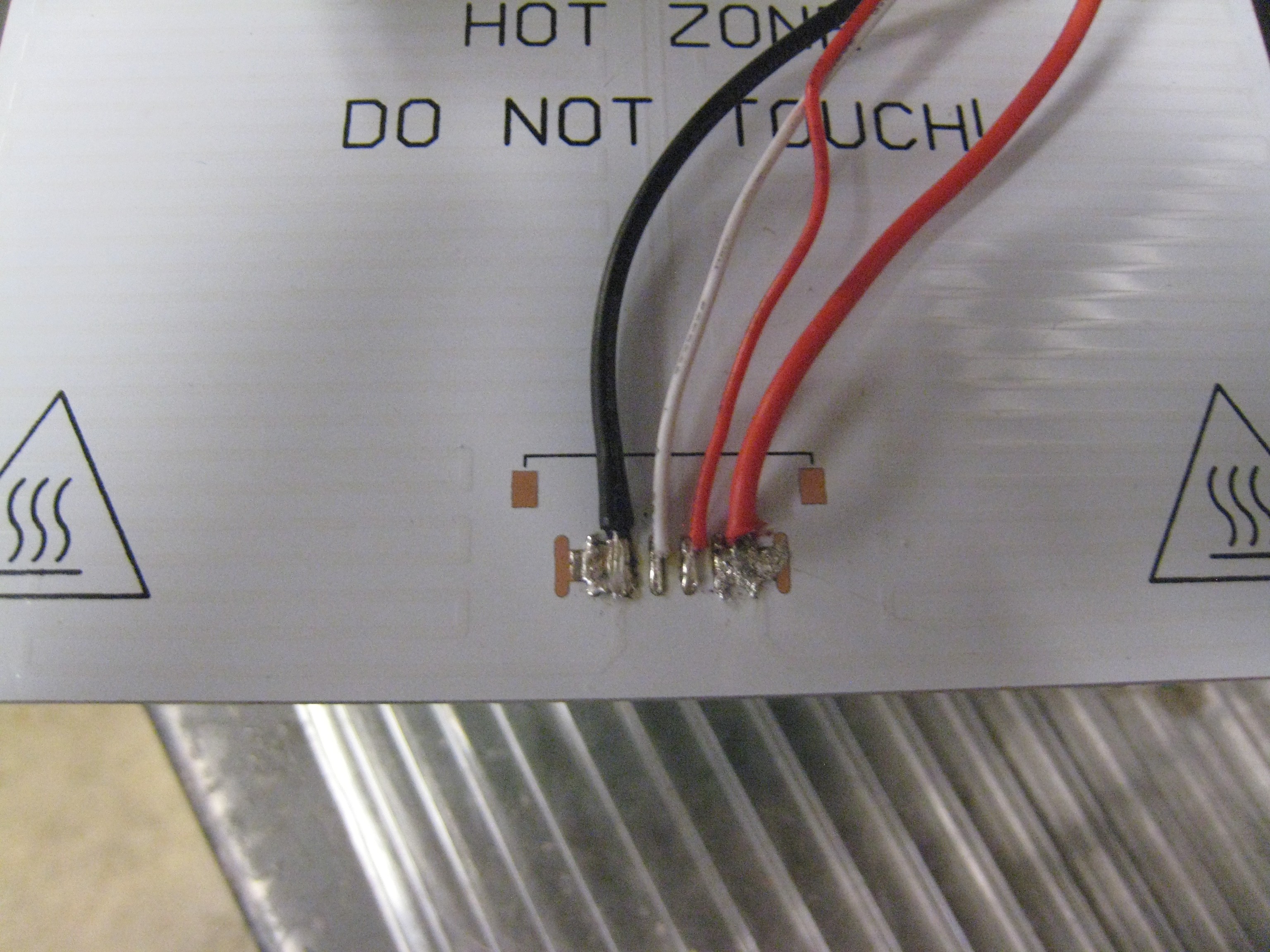
I then connected new wires to the original heater, pointing outwards and soldered wires to the new heater, using polyamide tape for insulation.
---------- more ----------
---------- more ----------I started with a 12 volt relay and a spare 12 volt 10 amp power supply. The relay coil was connected to the original heater and the contacts switched the "slave" heater. It worked but the noise of the relay was annoying so I switched to using a mosfet. I has some AOI510 mosfets around so I used one of them. They are rated at 30 volts and 70 amps with an on resistance of 2.5 milliohms when the gate is driven by 12 volts. Great little devices. At 10 amps it will be dissipating only 250mw so it doesn't need a heat sink but almost any mosfet will work for this. For neatness, I hacked a quad mosfet pcb I had designed for switching light strips using one channel and adding extra connectors by cutting traces etc.
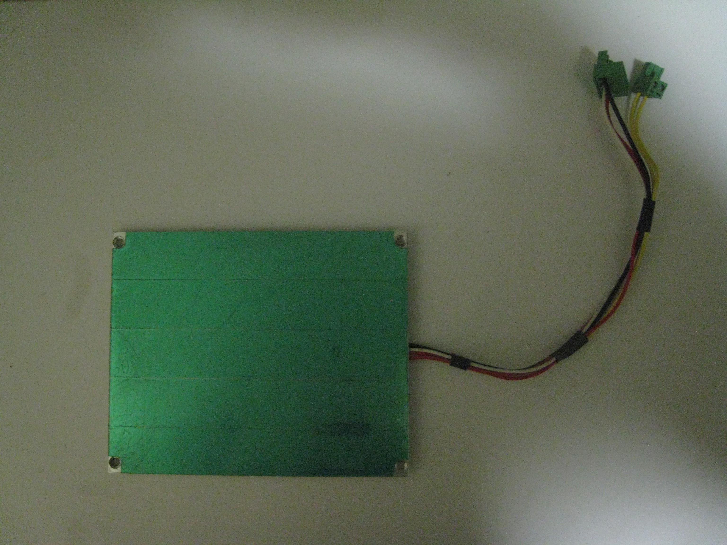
Here is the controller in a small box.
 The mosfet is in the middle on the left. To the left of it is the input connector for the second PSU. To the right of it is the connector for the wires from the controller. Above that is a four pin connector for the original heater and a two pin connector for the new heater. I have a gate protection resistor installed but in this application it is not required. There is also a LED on the right showing when the "slave" heater is operating. The circuit could easily be wired on some stripboard.
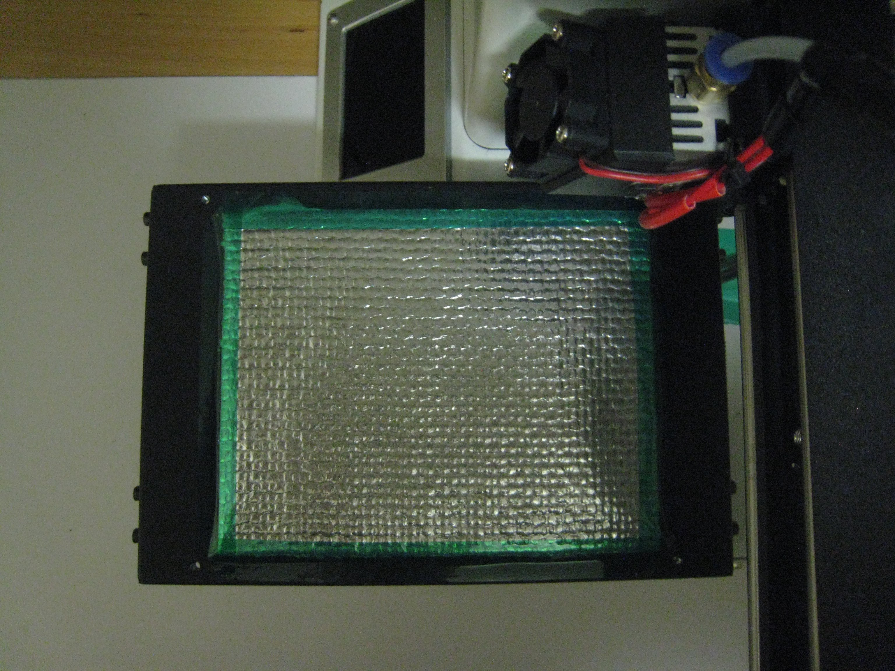
Here is the completed bed assembly. It can now be plugged and unplugged from the controller.
 The picture at the introduction of this project shows a rear view of the printer with the bed reattached. The control box is double sided taped to the back of the printer. The bed wires now come out from the back of the bed to the control box and the printer wires come from underneath the bed platform to the control box. These wires need to be taped down to miss the bed as it moves. Also the bed heater wire grommets on the bed and printer chassis are removed for clearance.
I also added some insulation on the platform to increase the efficiency. This insulation material is used on autos. It is a nomex material with a reflective coating. The slave heater wires must be covered with tape so that they can't be shorted by the metallic coating.
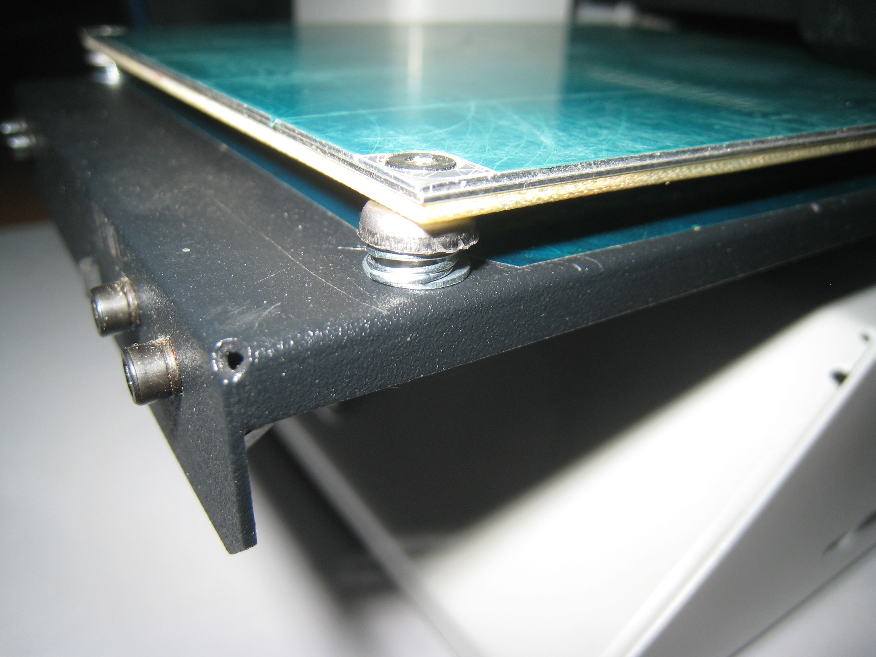
 Below you can see the side view of the new bed "sandwich".
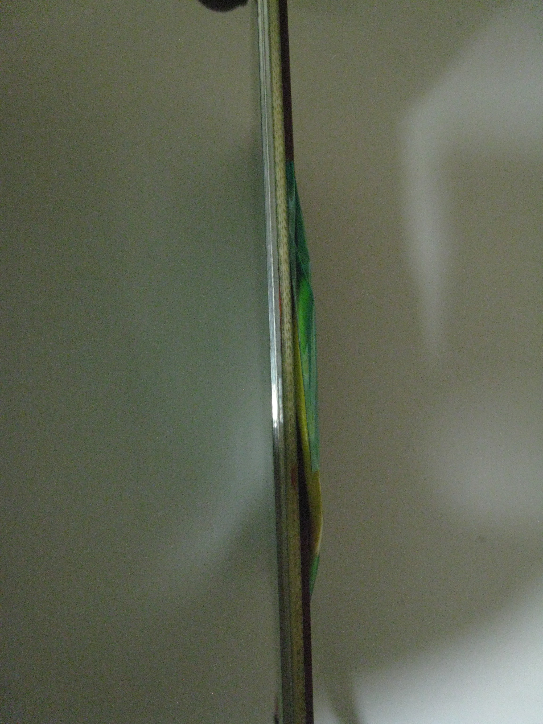 Withe the extra thickness of the FR4 under the springs, they will now bind when the bed is levelled. I found some shorter springs and used a flat washer on the bottom to avoid this.
 You could also cut away the FR4 or add a spacer to the limit switch as people who add glass beds do, but this worked well.
Now the bed will easily heat to 110c which is great for ABS and the bed is much stiffer and flatter. You do though need to give the bed ample time for the temperature to stabilize at there is a lot of thermal mass. Also you have to use print files to set the temperature above 60C. I have a set of pre-heating files at 5 degree intervals for that.
I use polyamide tape on the bed, sanded with 600 grit wet and dry to increase adhesion. For some ABS I need to use an ABS slurry for adhesion but it mostly needs no bed adhesive once the bed temperature has stabilized. The heater cost $14.50. A 12 volt 10 amp PSU can be bought on Ebay for around $15 ans the mosfet , wires, FR4, glue etc. cost around $5 to $10. I hope you find this useful.
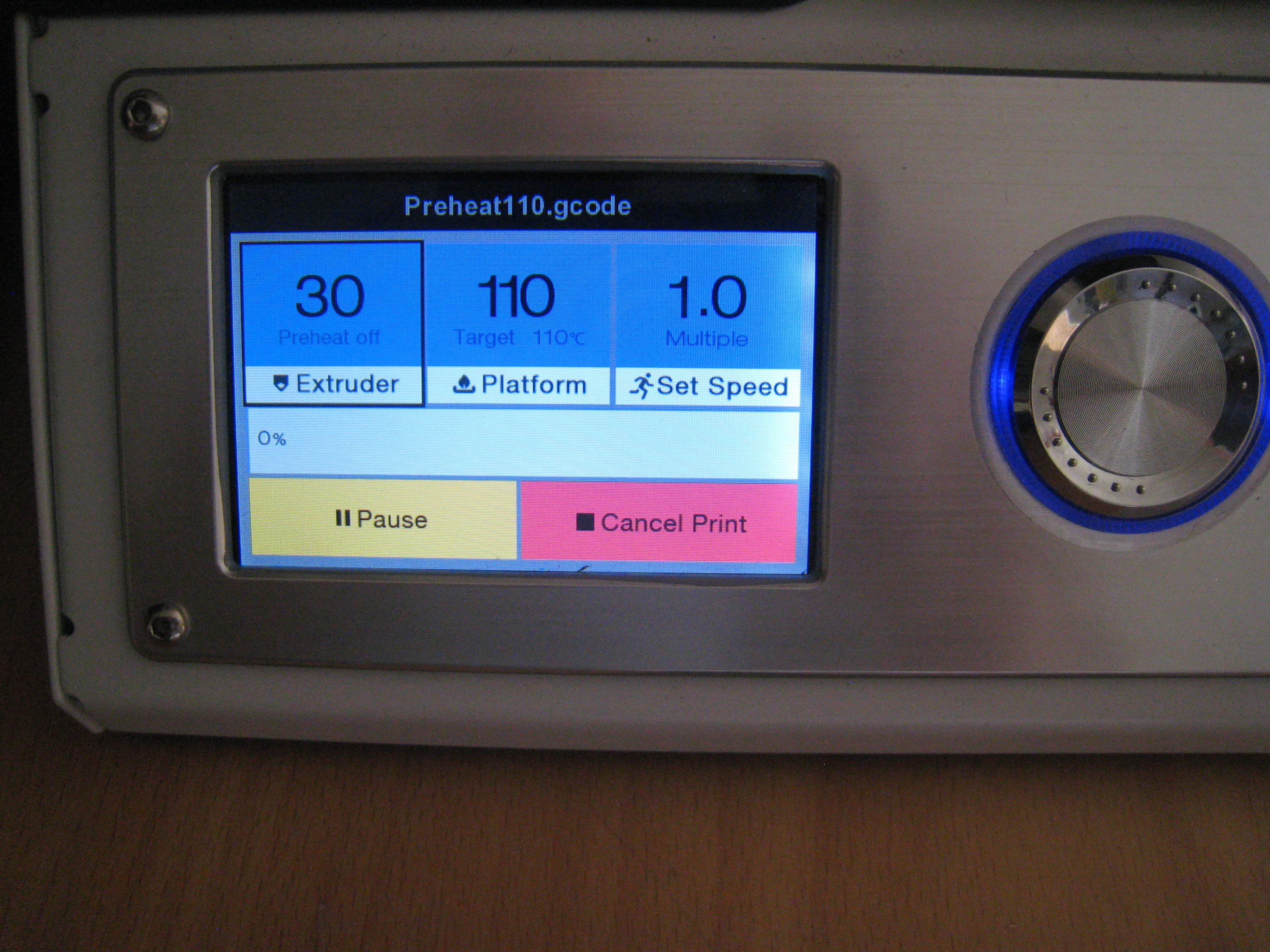
 Below is a screenshot showing a set temperature of 110c and an actual temperature of 110c. I assume the heater is driven by PID code but it worked well without any changes to PID settings.