Close
0%
0%

RabbitDueOpenECU

DIY Automotive ECU with ARM Cortex M3 Arduino Due Controller

Similar projects worth following
This project is made up of a prototype "Rabbit ECU" shield PCB and the Arduino Due controller. The test car is a Holden Barina (Opel Corsa C14NZ engine) but the system should be able to run 1, 2, 4, 6 and 8 cylinder engines.
The plan is to create a powerful low-cost open source hobbyist ECU using an up to date ARM micro, CAN bus and LSU4.2 wideband control all for around $100.
Right now I have been checking the hardware using the Arduino IDE but am planning on porting an RTOS to gain better performance from the SAM3X8E.
I am very open to ideas on the best way to develop the software being mostly new to Arduino and would be happy to have any SAM3X8E familiar people get involved!

In this project I want to create a cool creative interactive ECU shield that works with the latest ARM based project boards (for this project Arduino Due). The hardware features of the ECU shield are:

  • 1 peak hold driver for the batch firing low impedance injectors
  • 4 saturated injector drivers
  • 4 igniter signal channels
  • 10 general purpose medium current drivers
  • 4 push pull motor drivers
  • 1 LSU4.2 interface
  • 1 CAN interface
  • 8 analog inputs
  • 2 multi trigger inputs

The hardware is mostly complete and I am testing it now. So most of the project work will be developing software for the SAM3X8E micro in the Arduino Due. There is quite a bit of development and porting to do so if anyone is interested and has some ATMEL insights then please get on board! It would be also great if anyone is game for a multi injector multi coil application.

9Relays.pdf

Adobe Portable Document Format - 16.89 kB - 08/19/2016 at 12:05

Preview

3WideBandSensor.pdf

Adobe Portable Document Format - 21.53 kB - 08/19/2016 at 12:05

Preview

14CAN.pdf

Adobe Portable Document Format - 12.28 kB - 08/19/2016 at 12:05

Preview

5SatInjectorDriver_X.pdf

Adobe Portable Document Format - 13.70 kB - 08/19/2016 at 12:05

Preview

4Injectors.pdf

Adobe Portable Document Format - 12.97 kB - 08/19/2016 at 12:05

Preview

View all 15 files

  • 1 × Arduino Due
  • 1 × Rabbit ECU Shield

  • May 2020 Update

    matthew05/31/2020 at 04:19 0 comments

    Rabbit ECU project has a new test car! After a 18 months of testing and daily driving the VE Commodore SS L98 engine project, it seemed like a good time to move on to a more high-tech platform.

    The new test car is a VW GTI Mk6 with EA888 engine.

    The EA888 family is an Audi-designed unit that features some of the latest engine technology such as direct fuel injection, variable valve timing and lift for intake and exhaust valves, distributorless coil-on-plug ignition and fly-by-wire throttle. Being a VW car, it is very often mated with a DSG electronically controlled gearbox.

    The EA888 is the first GDI engine to be tested with the Rabbit ECU, and required the creation of some additional hardware to be able to hack the CAN bus that controls the DSG, and also add high voltage support for the injectors.

    You can see the prototype hardware support board (I call it Sparkdog PF-DI) along with the Rabbit ECU running the engine in these videos:


    This project log is concerned with studying the VW CAN bus and DSG in order that the DIY aftermarket Rabbit ECU can control the gear selection. At first this seemed like a daunting prospect!

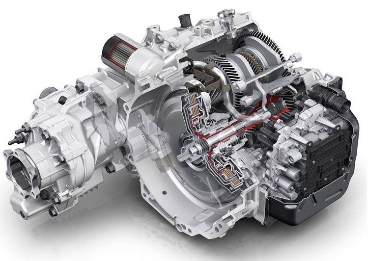
    But taking a closer look at the DSG reveals its simplicity - there are only power and CAN connections to the single DSG connector (see far right side of picture below). This is very different from a first generation electronic automatic transmissions, where the engine ECU was typically connected to pressure control and shifting solenoids, as well as sensors and switches.

    So integrating the DSG with the Rabbit ECU is clearly a matter of CAN study and understanding, and replacing the messages lost when the Bosch OEM ECU is removed in favour of the Rabbit ECU.

    To observe the CAN messages, I used the excellent 8devices Korlan USB to CAN converter, and connected to the VW powertrain 500 kbps bus by adding a d-sub connection stub close to the OEM ECU.

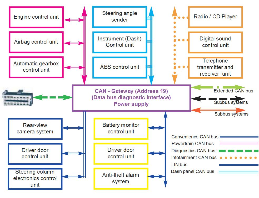
    Unlike many cars, there is little point connecting to the under-dash OBD port because there is a gateway that stops the free flow of powertrain bus information to that connector.

    Understanding how the DSG system works takes both detective work, and 'thinking like' a transmission ECU such as the one embedded inside the DSG. Or at least like an software engineer who writes code for one.

    The 'need to know' information that the DSG controller would include at minimum:

    1.  Gear selector position
    2.  Brake pedal status
    3.  Engine estimated torque output
    4.  Pedal position
    5.  Throttle position
    6.  Manifold pressure
    7.  Engine temperature
    8.  Engine speed
    9.  Vehicle speed

    Some logical thinking into the problem, and also a study of the VW GTI Mk6 wiring diagram should lead the hacker to think that this data should be transmitted over CAN from the gear selector module (selector position), engine ECU (engine speed, temperature, etc) and ABS ECU (vehicle speed and brake pedal position).

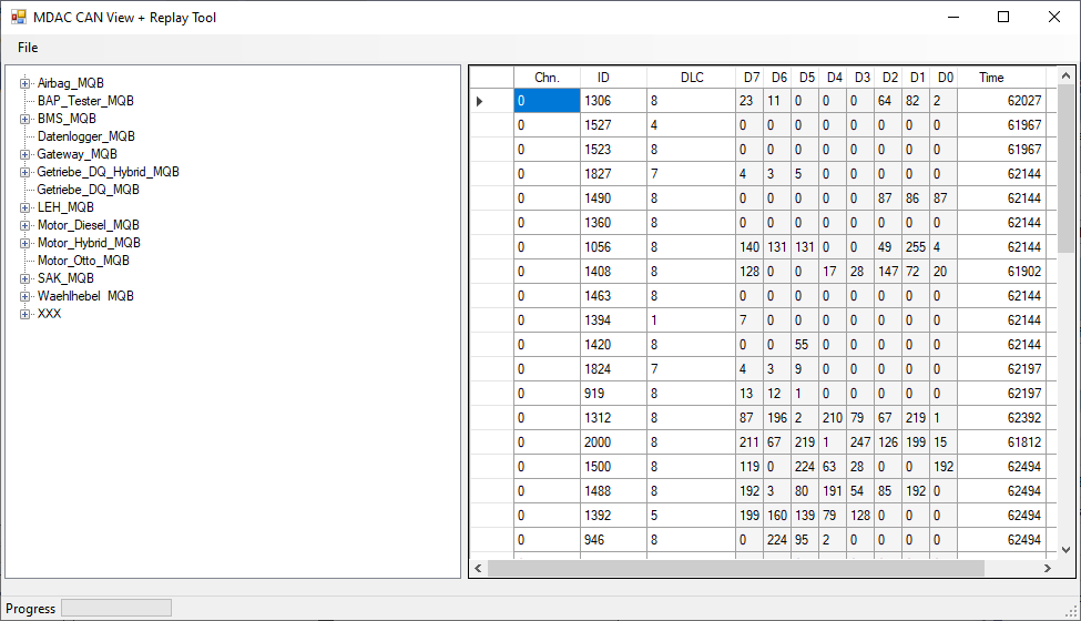
    And so the detective work starts. For CAN hacking, I use the MDAC CAN View Replay tool, connecting through Korlan.

    Here is an example of a CAN message list of the powertrain CAN at key on.

    By observing the CAN message list and changing the DSG shifter position, engine speed, vehicle speed and other conditions, it is possible to identify the byte positions of the data that is needed.

    For example, observing CAN ID 640 the pedal status idle, open and maximum are contained in the first byte. Engine speed follows in the next two bytes.

    At CAN ID 648 the coolant temperature is found by observing the data as the engine warms up after start. In this way, all of the CAN IDs and byte positions of data can be found.

    The work is ongoing, but you can see a video of testing below.

    The engine still needs some tuning before I can start increasing the boost above the stock ECU limits. Updates soon!

    If you like this project you can also keep in touch here on Facebook.

  • May 2018 L98 Engine Test Rig

    matthew05/28/2018 at 10:57 0 comments

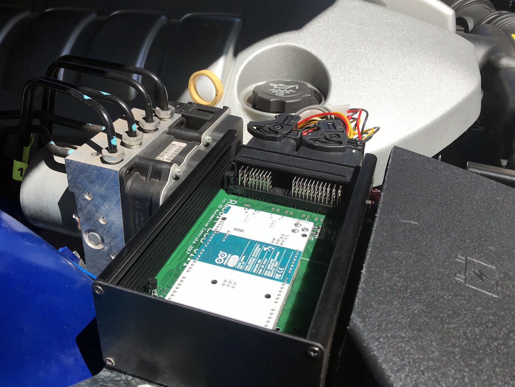
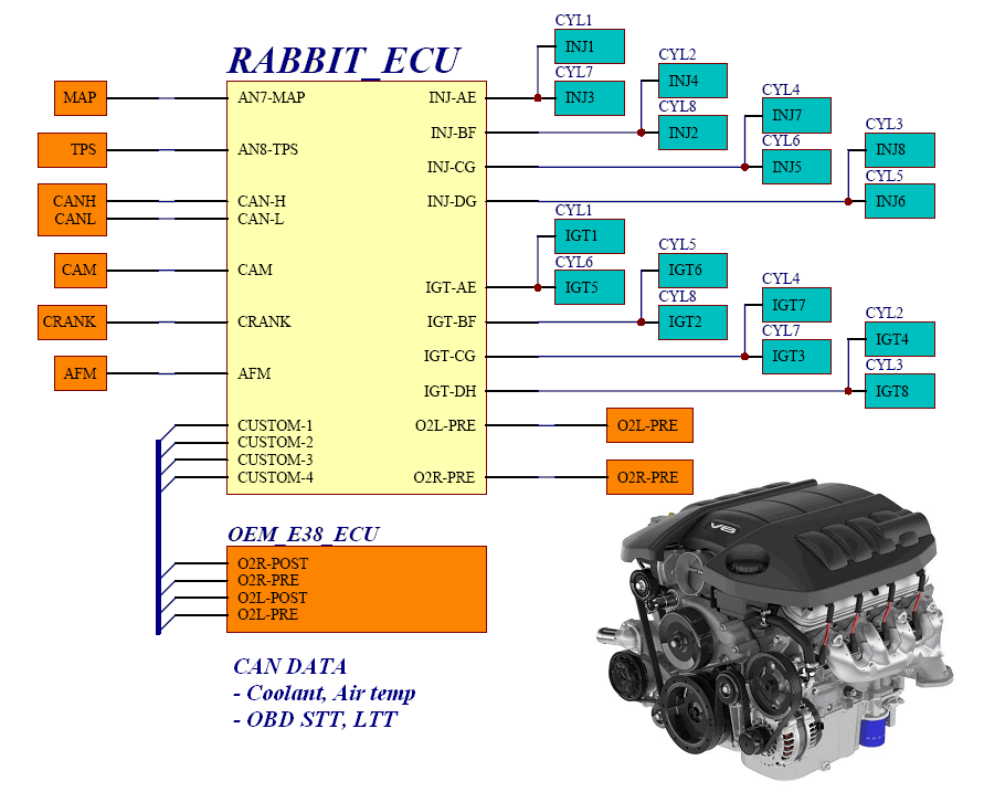
    The Rabbit ECU project test car is now a VE Commodore SS (Chev SS). As you can see the ECU sits in between a fuse box cutout and the ABS controller. 

    The Rabbit ECU runs piggy-back in this setup, having total control over fuel and timing but leaving the OEM ECU in place to control everything else.

    Injection is semi-sequential because the Rabbit ECU has 4 saturated injector outputs. There are also 4 igniter outputs so the system runs wasted spark.

    Here is the wiring harness that allows the Rabbit ECU to hack into the OEM system.

    Getting a piggy-back ECU to run happily with a late-model OEM system is a bit tricky. CAN integration is pretty much a must to get up and running without setting off the check-engine lamp.

    The Arduino Due controller used has 2 CAN 2.0 controllers on-board so connecting to the OEM 500 kbps bus is pretty straight forward.

    The Rabbit ECU reads signals such as air and coolant temperature, vehicle speed, throttle and pedal position right off the periodic CAN messages.

    To get full integration with the system it helps to also grab OEM tuning parameters short term and long term fuel trim over OBD CAN, along with the OEM timing angle.

    The OEM ECU really throws the ignition advance around at low rpms to get a stable idle. It is better to just eavesdrop on the OEM ignition advance and use that value to get a good idle and little timing kicks when the AC comes on or there is a power steering load.

    Wiring up a system like this involves making around a dozen wire splices, and adding an extra injection/ignition harness from readily available connectors.

    If you're interested in reading more about hacking your OBD for a piggy-back install check out this link.

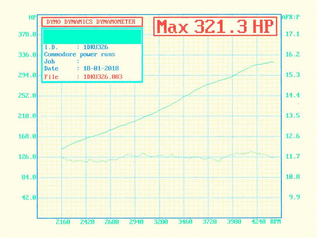
    Does it work? Here is a dyno plot from an initial run, very rich and rev limited.

    Next steps is to add some custom inputs and outputs to control dry nitrous, and to tune a little leaner for more power.

    You can see it run here and here.

  • New Test Engine - Z18XE

    matthew04/18/2017 at 12:31 0 comments

    This project pretty much hit the limit of what you can do with a simple throttle body injected engine. Basically not a lot!

    So time for a new test engine - Z18XE that comes with OEM Siemens 60-2 crank trigger, 1 tooth cam sync, 4 cylinder sequential injection, direct fire coil-on-plug ignition, electronic throttle control and hot-wire AFM.

    The Rabbit Due Open ECU was in need of a tricky crank trigger test. The magnetic reluctor 60-2 seemed like a good start. So far so good, with the Rabbit ECU running fuel only batch-fire injection. The Siemens ECU is still running ignition and electronic throttle control.

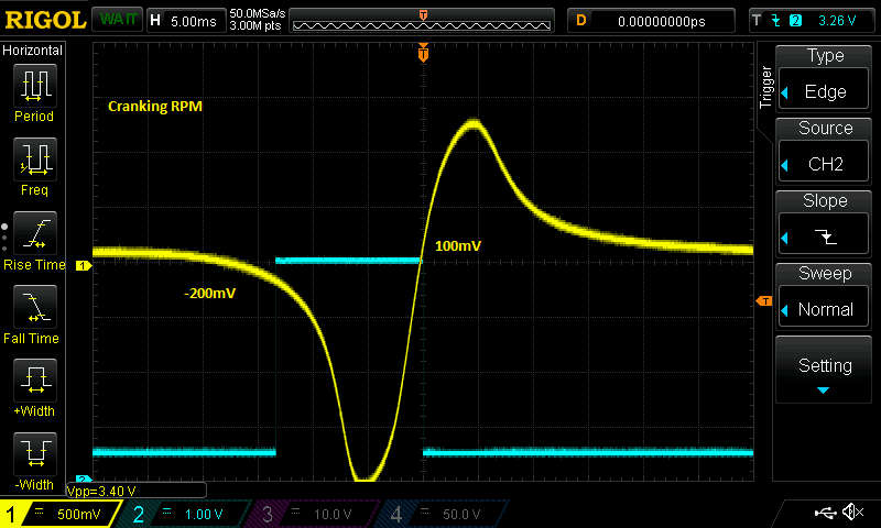
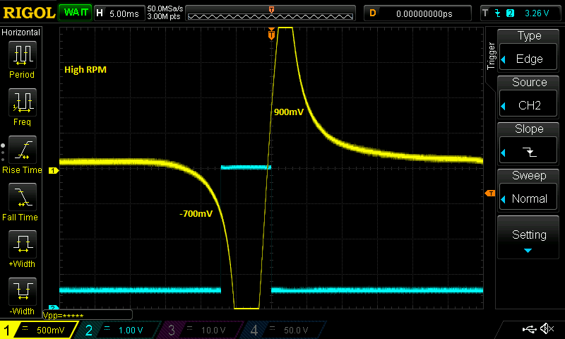
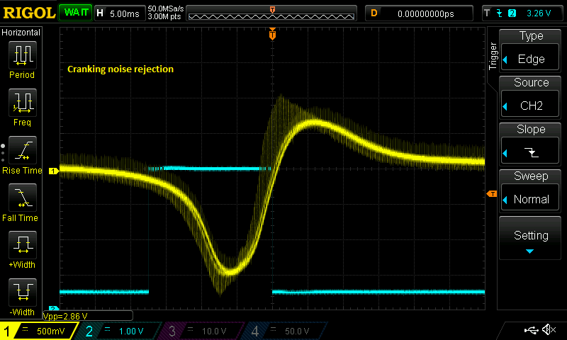
    In the coming weeks I am hoping to test the Rabbit ECU reluctor adapter (VR) circuit a lot more. One nice feature of the circuit is the ability to set the hysteresis thresholds in software depending on engine speed. So good pickup of a weak cranking signal along with high resistance to noise at high RPM when nasty VR cross-talk occurs.

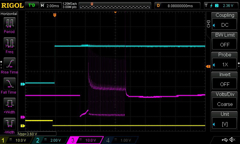
    You can see in the last scope the circuit seems pretty robust to noise on the bench at least.

    Next step for the Rabbit ECU project is working with the hot-wire AFM. So far the car runs nicely but hooking up an AFR gauge will tell us more...


  • February 2017 Update

    matthew02/28/2017 at 00:26 0 comments

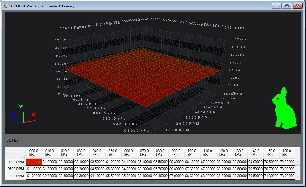
    Rabbit Due Open ECU now has 3D mapping! Up until the last few weeks, the timing and volumetric efficiency maps were both a combination of 2D tables. The timing advance was just like a distributor; advance = speed advance + vacuum advance.

    This works pretty well for a simple engine. But you can get a lot better result with 3D mapping. Over the next few weeks I am hoping to have the C14NZ engine running a lot better with a nice 3D tune. Shown here is the base volumetric efficiency 3D map.

    In other exciting news the Rabbit Due Open ECU can now be found in kit-form at our tindie.com store!

  • December 2016 Update

    matthew01/03/2017 at 11:29 0 comments

    Great progress to end 2016 - the Rabbit Due Open ECU has first start on the C14NZ engine!

    The starting and drivability of the engine is quite good after a few weeks of code updates. The ECU has been happily running the engine as a daily driver for a few weeks now. The only major things missing right now are the stepper motor idle speed control and the factory narrow band closed loop control, both of which I hope to add in the coming weeks.

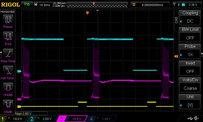
    The saturated peak and PWM hold injector driver seems to be pretty robust and has the advantage of much lower heat dissipation compared with old-school linear low impedance injector drivers.

    So far it seems that the Arduino Due SAM3X8E project board is a great controller to use with a shield style DIY ECU like the Rabbit. The availability of multiple timed outputs, analog inputs and CAN bus is useful for all sorts of DIY EFI, sensing and data-logging projects.

    After the ISC and closed loop control is done, the next step will be to look at the differential mode AD converters for implementing the LSU4.2 wide-band exhaust sensor interface.

  • October 2016 Update

    matthew11/15/2016 at 14:23 0 comments

    I've been working in my spare time during October to link the SAM3X8E hardware to the existing ECUHost OS. The good news is that coding peripheral modules for SAM3X8E is mostly taken care of by the excellent ATMEL ASF software framework.

    So progress has been pretty good, with digital I/O, analog inputs and timed inputs mostly done (as far as the test engine needs anyway). Next step is to get the timed outputs working for fuel injection and spark timing! I am hoping to get enough of the ECUHost OS working with the SAM3X8E that I can run the engine by the end of November.

    There haven't been too many changes needed to the OS, interrupts and service calls between the NXP Kinetis (first implementation) and the SAM3X8E - there doesn't seem a lot of difference between Cortex M3 and Cortex M4 from the programmers point of view.

    I think these ARM micros are are great basis for a programmable after-market or hobbyist engine management system!

  • September 2016 Update

    matthew10/02/2016 at 12:45 0 comments

    The Rabbit Due Open Source Engine Control Unit (ECU) software is build upon the ECUHost RTOS. This free and open-source RTOS is targeted towards automotive DIY projects and runs great on the Freescale Kinetis Cortex M4 micro-controller.

    I am hoping to create a system where the user can run a Arduino IDE created sketch, or and ECUHost application. A bit like a dual-boot PC!

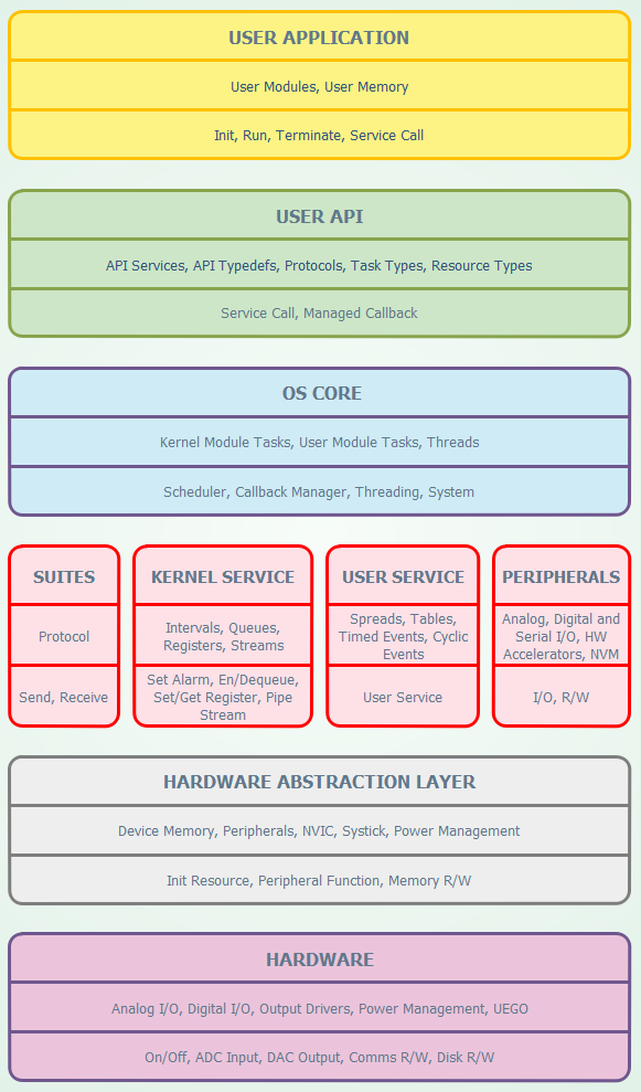
    I have been doing a fair bit of work during September adding a hardware abstraction layer (HAL) which should hopefully make porting to the Arduino Due Cortex M3 SAM3X8E micro-controller straight forward. This involves adding 'HA.c and 'HA.h files for each code module that isn't platform independent. Not platform independent just means that the module reads or writes to CPU registers or special memory locations that are unique for the micro-controller family. Hopefully you can see the concept in the system layers diagram below (look at the second lowest layer - HAL).

    ECUHost System Layers Diagram

    So progress in September was basically adding all of the required files in Atmel Studio 7 and working on the source code until I could get a compile. Next step get debugging!

    All of these efforts can be seen here:

    https://github.com/RabbitECUProject/RabbitECUOpenHALTrunk

    What Next?

    Aim for October - see how much functionality I can add to the HAL layer files for the SAM3X8E Arduino Due micro-controller.

    I am hoping to have the analog and timed I/O working so I can do some bench testing before running the Rabbit Due Open ECU on the C14NZ test engine.

View all 7 project logs

Enjoy this project?

Share

Discussions

matthew wrote 02/15/2018 at 23:59 point

Hi David,

Sounds like ignition system electrical noise upsets the Arduino probably from your crank position input. Take a look at http://www.mdac.com.au/wp-content/uploads/2017/11/2CrankCamMultiInterface.pdf this is the crank/cam input circuit you might get some ideas how to low pass filter your inputs and add some hysteresis (aka Shmitt trigger) to avoid this problem.

Cheers and good luck

  Are you sure? yes | no

davidesalama1 wrote 11/26/2017 at 13:50 point

Hello.

I made one ECU only for the Ignition system . It works OK without connecting the ignition coil.

Even tought I used TVS, 7806, capacitors and varistors allways the noises win and the arduino goes crazy.

Could anibody help me.

Thanks.

  Are you sure? yes | no

Similar Projects

Does this project spark your interest?

Become a member to follow this project and never miss any updates