Putting it all together
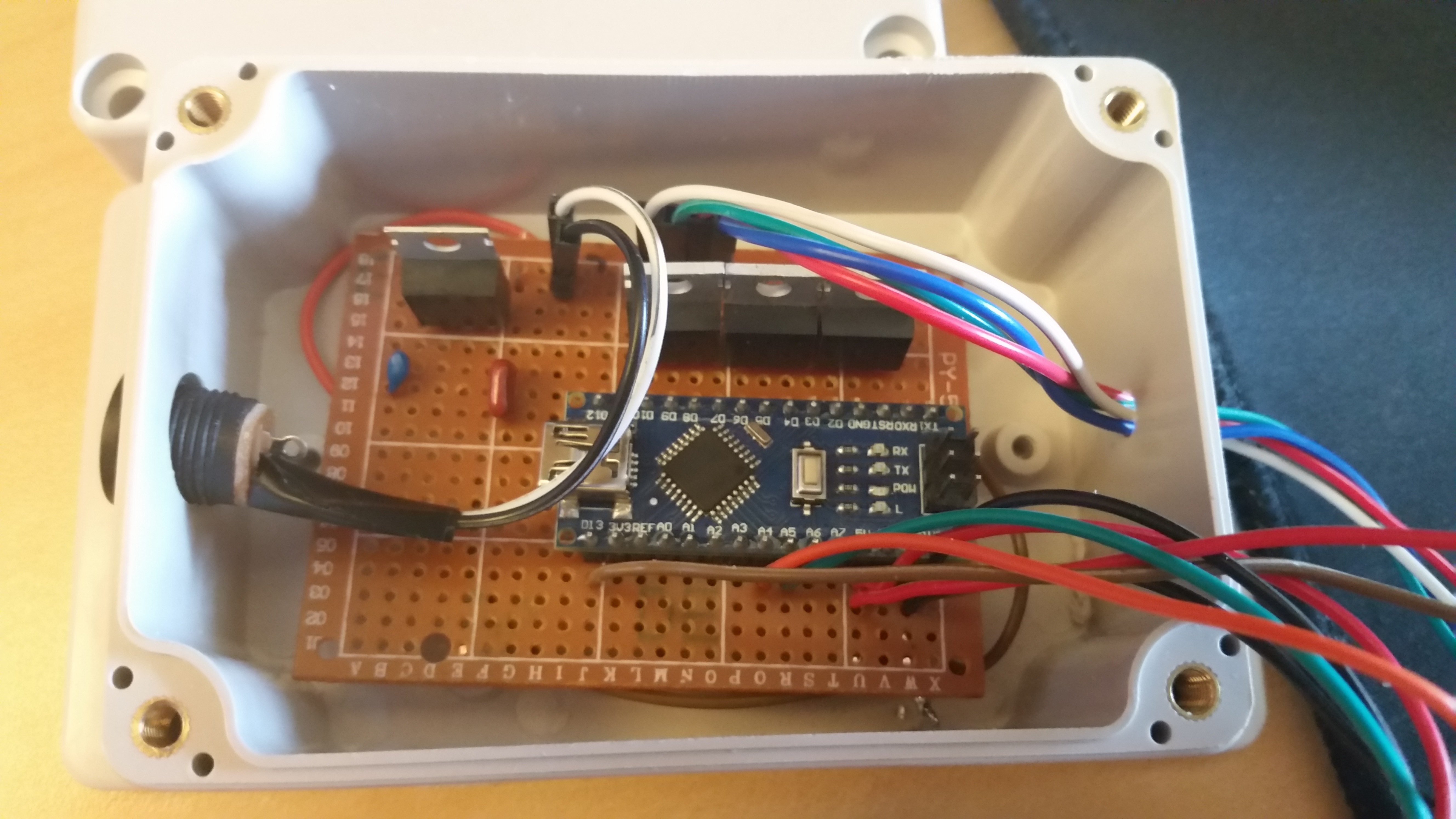
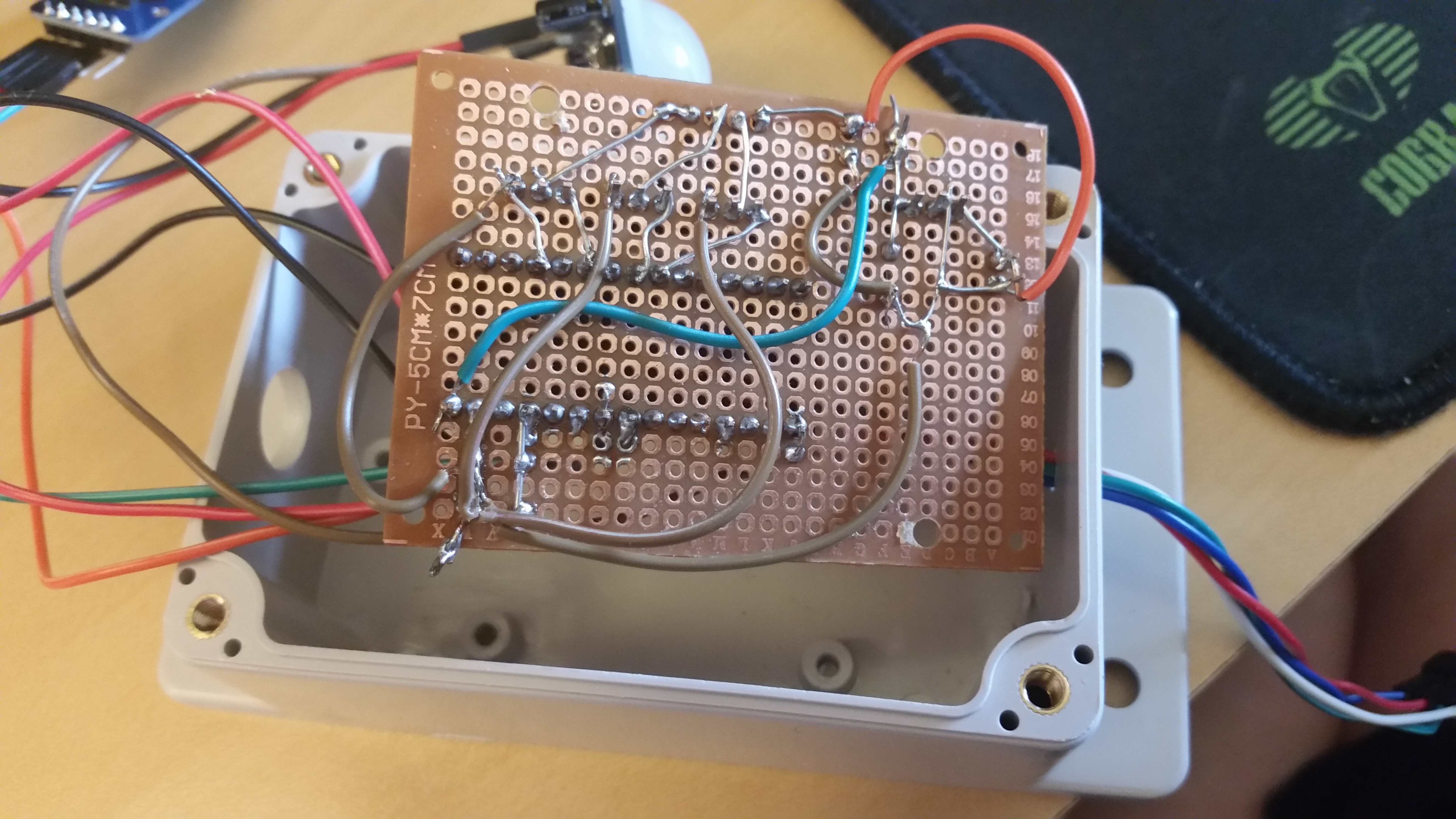
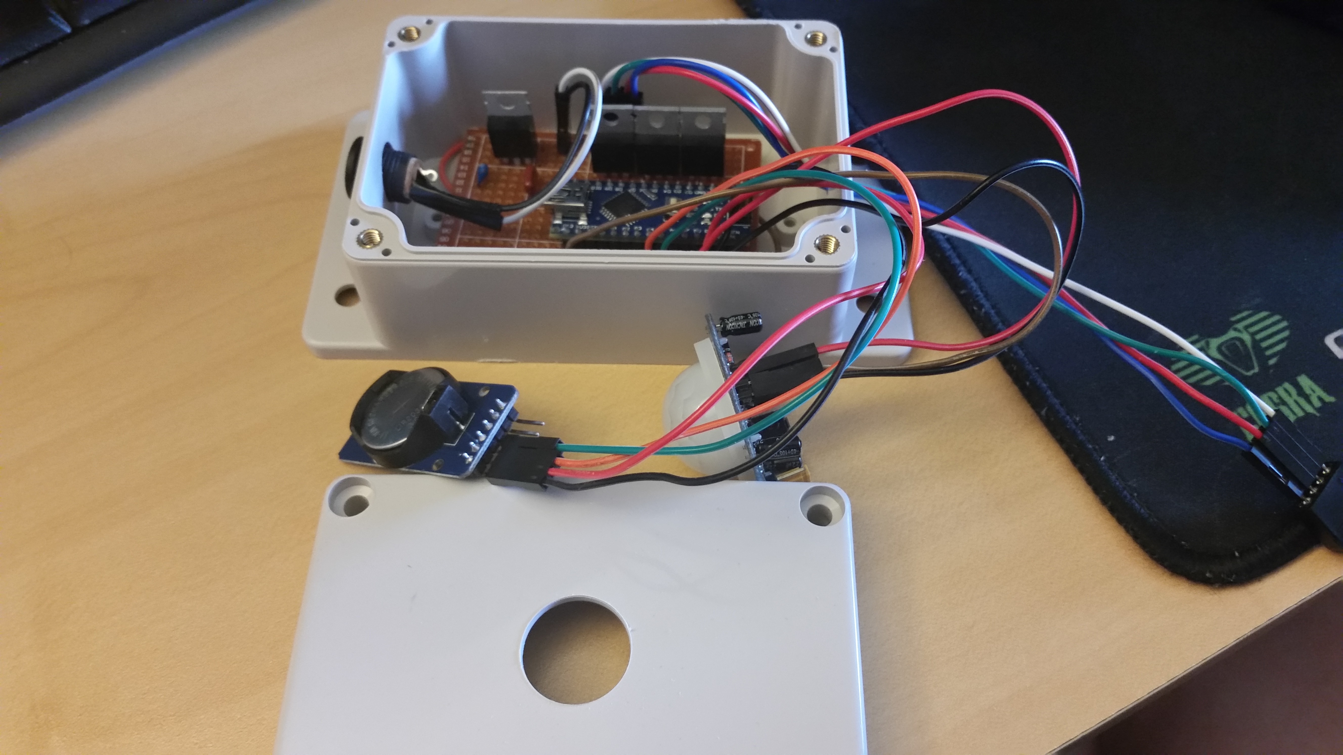
90% of the time spent on this soldering the components together. I relied on dupont jumper cables to keep everything modular and easy to attach/remove key components. Basic cheap protoboard is a bit of pain to work with, but is great if you want to throw something together in a couple hours.

You can check out the schematic on the previous project log to see what everything is. I used a 2A 12V power supply for this. These LED strips can draw a lot of current!

For short jumps I used resistor leads, for long jumps, light cable.

Here is everything all connected. Besides needing a larger bit to make space for the motion sensor, all the work on the case is done. It will be a tight fit, and I kept the wires a bit long, but it should be good to go. With all of it together I was ready to start testing.
First Tests
Things seemed to work great. I was able to set and then read the RTC. If the RTC hour value was > 20 or < 9 the micro would check the status of the motion sensor. While the motion sensor pin was high, the light show would go off. If the RTC hour value was outside of the above range, the lights would not turn off despite the motion sensor being triggered.
Everything was going great until I heard a pop.
To be continued...
 Scott Clandinin
Discussions
Become a Hackaday.io Member
Create an account to leave a comment. Already have an account? Log In.