Mangus Tiranus
-
Admitting defeat... V1 project, maybe dead... Maybe...
12/08/2017 at 12:47 • 0 commentsWell this is sad. I really didnt want to post this but the last few weeks I've been really struggling and contemplating doing this...
I have to admit defeat. This version of the project is now dead. Which is a painful shame given all the hard work ive put into it.
So whats happened?
The custom FTDI EVE display i designed... I just cant get it to work. I've spent the last few months going over it, I went through 3 different PCB designs on paper it should work but it just does'nt. Part of the problem is the LCD panel itself.
It uses an ILI9488 chip, and datasheets for the real nitty gritty how to get this to work is scarce. For starters, in the mian datasheet it says to get teh display running in 18bit parallel mode you only need to set the IM0,1,2 pins to 0, I've tested this both as floating/unconnected or low to ground. Neither automatically sets this to the correct mode.
With James Bowman from Gameduino we worked out that the datasheet is actually wrong, and to get the display to work You have to first set it to serial mode, then send a bunch of undocumented commands to the chip to flip it into the correct mode. This is not written in ANY datasheet. its purely worked out from random bits of code found online from various Chinese sites.
I've had a huge amount of help from James trying to get this to work. hes even written a whole article on how to get ILI9488 displays to work on the FTDI EVE, you can read it here: http://www.excamera.com/sphinx/article-ili9488.html
And we nearly got it working, if it wasnt for James I would have posted a post like this weeks ago...
So heres whats happening with the display...
Considering all the resoldering and 5V logic ive been putting this through, its possible Ive now damaged one or two or more parts and it would never work correctly...
Also my bike stuff has changed, I'm now in the process of getting my full bike license and I have a new bike already, A Kawasaki ER6f... Given that I have a nice new bike, and this isnt working. I dont want to throw any more money at this project :/
I wasnt aware before about the bridgetek display James mentions in the article beforehand. I could buy one of them and that would solve this and I could get on with programming and finishing the project, but its more money than I'm willing to spend right now for this. ($49, roughly £35)
By all means if anyone is willing to donate me a bridgetek display, ill carry on the project with that :)
The main board works, the LEDs work... and looks great. The power requirements for them is a little high and so I might replace the vRegs with buck converters if I continued. But thats only when it runs at full white bright that they get HOT! i normally only run them at 50%
So where does this leave this project? No I am not killing the project as a whole. just V1, I had always envisioned a more advanced V2, only that originally it was going to look some what the same with analogue dials and a screen in the centre...
This would now likely be using a prebuilt 5 inch display from HOTMCU, so I wont have to worry about messing up its design.
One of V2's key features would be GPS tracking for theft recovery with no subscription charges, using a free mobile provider like Freedompop to handle the minuet bandwidth requirements. So you find your bike is missing, you text the bike a command like "Where are you?" And it fires up the gps and replies with a gps location. it would then ask if you want real time updates? which you reply yes to and you then get a link to your phone with map and regular updates being posted online.
This could be linked to a google account or some other service. i've still yet to work out the details on that. i might even design an app for the phone that the bike connects to through the internet and provides the location info to. V2 is very much a product version of the digital speedo. Something I want to develop to sell.
So yeah, for now it seems, this project is kinda some what dead... Maybe CPR can save it... money could save it but with my recent costs I just cant afford to put any more into it.
-
Something is coming, a sneak peak
08/19/2017 at 17:11 • 0 comments![]()
![]()
Still a ton of things to do, but I am starting to put together the new prototype.
Ive been playing with my new 3d printer this last couple of weeks and still need to do some more work on it before making the main case. But hay some news, its coming together. Expect a proper update in a few weeks... (i ordered the wrong diodes so its going to be at least 2 weeks for the new ones to turn up >.< )
-
So whats been happening
07/23/2017 at 10:39 • 0 commentsIve noticed a fair few more followers recently and because of this I thought Id give an update on whats happening, so people know the projects far from dead.
Well things have slowed down because of a few issues at home... Family trouble, fun eh?
So it might be another month before theres a real hardware update on everything.
But I've been doing tons of work on the computer towards having a functioning 'attached to the motorbike' prototype final build for V1.
I had some pcbs made by easyEDA and they looked great, only trouble was I roushed it and made a few little mistakes in the design.
Also the LCD i got was unsuitable as I couldnt find a touch panel to fit its unique aspect ratio...
So Ive now found a new display its a little larger at 3.5 inches but actually it fits better for the design.
I've been finishing up the case design in CAD (f360) with only a little bit left to do, i need to design some kind of bracket for the speedo to mount onto that connects to the bikes frame.
Ive also designed a speed sensor that fits into the casing. This is just a disk with magnets and a hall effect sensor reading the disks rotations. This gets attached to the bikes speedo drive cable that comes off the wheel.
And the other major thing, Im getting a 3d printer. Its being shipped as i type and I should get it within the next couple of weeks. Only trouble is because of the trouble at home I may not be able to go home to put it together and print out the bits.
I need to save a little to get new pcbs made as well as get all the components. But Im nearly there. Soooo sooo close. Once I got it made ill make another video update.
-
Onward and upward... And, oh hay, some renders...
06/02/2017 at 17:01 • 0 comments![]()
Well it seems the PCB renders i previously posted arent to be... mostly because I decided to try and reintegrate the LED arrays onto the mainboard.
This would half my PCB making costs and as Im going to get my next board professionally madeI thought the issues I would have had before with low yield or pcb damages shouldnt be a problem now.
Also whats new is the speedos going to get a slightly larger and higher res LCD display. This is because it was proving incredibly hard to find a cheap 2.8 inch display that was compatible with the eve chip. They existed but were just too expensive...
Though getting a 3.2 inch display hasnt been perfect either. Again finding a display wasnt so hard. But then none came with a touch screen film. So ive managed to find one that should fit and I can manually attach it to the screen.
The PCB design is nearly complete. I need to track up the LCD board but other than that the boards done.
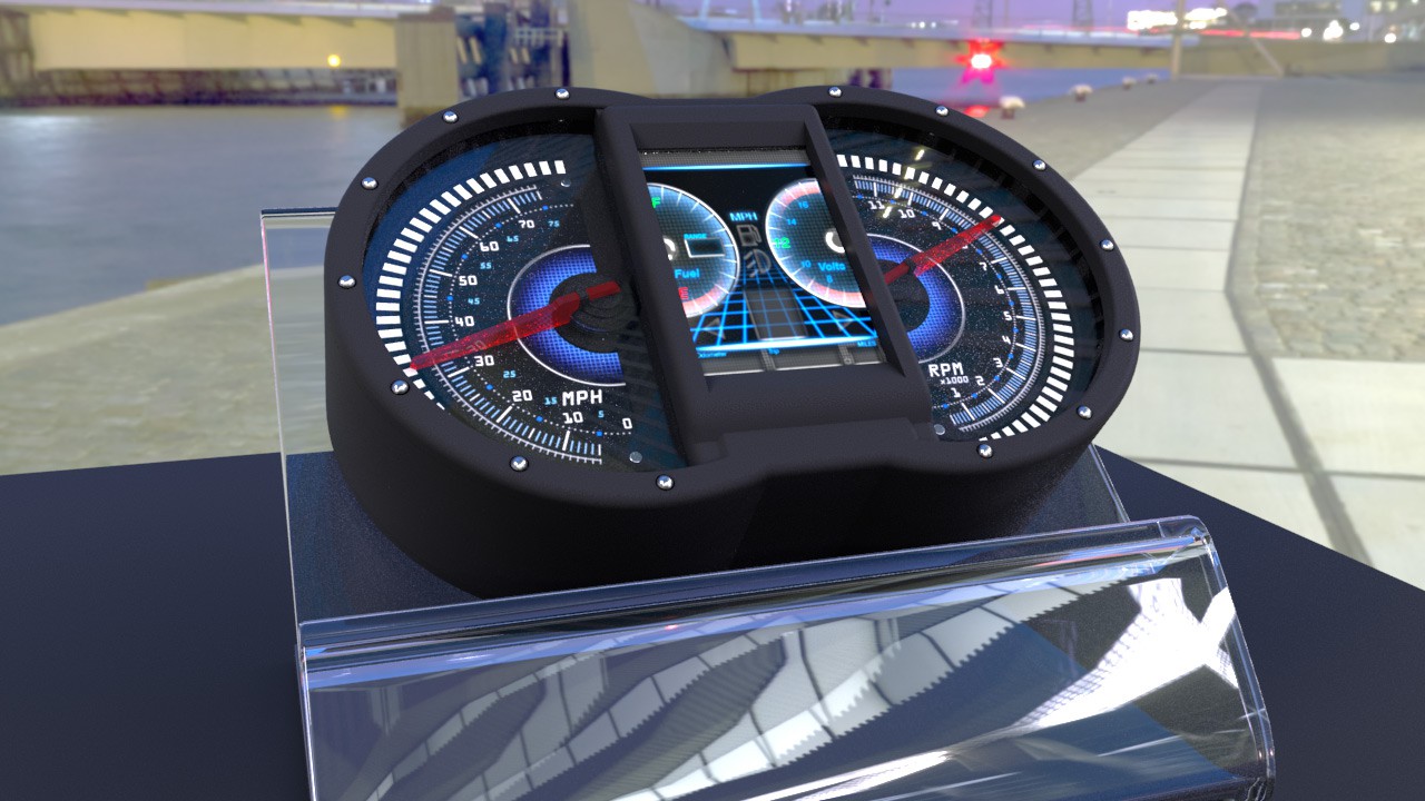
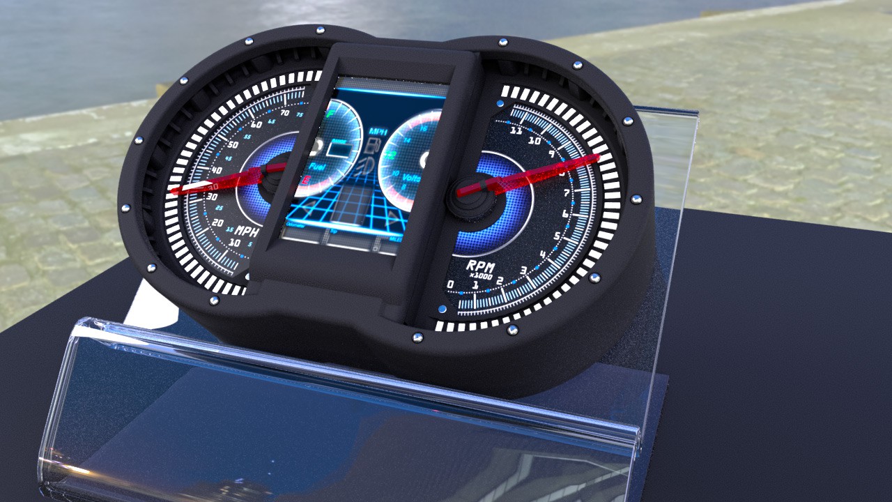
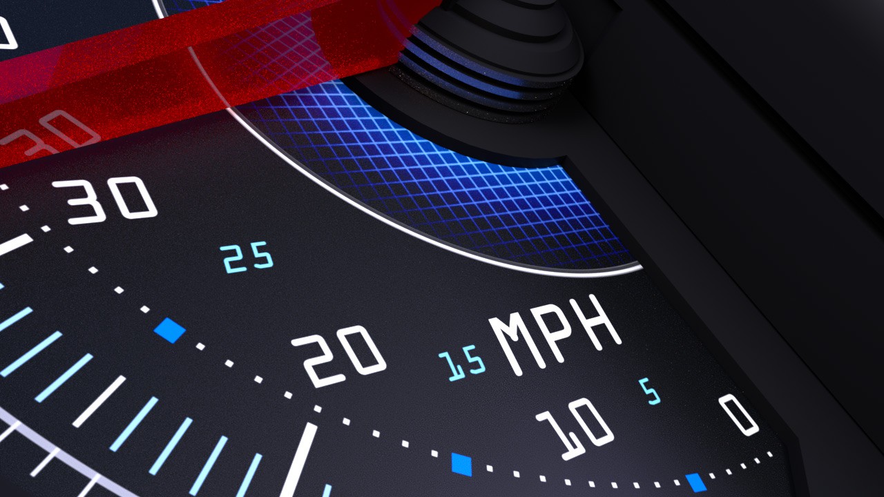
In the mean time ive spent some time learning Maya, as a Max artist ive been wanting to learn maya for a while and this is a perfect opportunity to mess about with it.
I made a new Cad project to fit the new board designed and imported that case to Maya, did some mesh cleaning applied some textures and churned out a few renders.
Sadly this laptop isnt really built for rendering so these take ages to render within arnold and theyre not perfect.
Anyway thought you might like to see them.
![]()
![]()
-
A setback, Maybe what I need!
05/06/2017 at 14:33 • 0 commentsWell Ive had a setback today, Today i discovered that Virtual Box works in mysterious ways...
As Im using a Macbook I had to run Vbox to use some small windows apps, this including the Nextion Editor for building the GUI on the lcd display...
A few weeks ago i did some house cleaning on my computer and deleted some unused large files. Including some Snapshots of the VM I used. I kept the main virtual drives I had setup believing my important files to be in those drives... only to today find out thats not how VBox works. It puts everything you to in the machine into a second Virtual Drive for some strange reason. Strange because that takes up a huge amount of space for no reason at all...
I recovery the VM got it working again and tried to find my files... Nothing. Its not there... All gone. All the Nextion Editor program and project files. Gone.
I still have the graphic assets as I made them in Mac. But the project gone...
There is some one who maybe able to recover some of the project from the firmware file. But it will still be a fair amount of work getting it running again.
Pretty gutting... And Yes I should have had a recent backup. But trouble is with all the stuff going on in my life at the moment. Backing up has been the last thing on my mind.
I do have a backup but its old. its from when I had to move out of home so late January...
But silver lining... This might be the kick I need to finally make the proper move over to the EVE display solution. Im already designing my mainboard with the ability to use an EVE setup. But Im currently struggling with making the display board itself. I need to find and stick to one LCD panel but finding one is proving more complicated than I had hoped.
In either situation. I have a lot of work to do... If i can recover the project in a partical state I have a fair bit of work to fix it. But it would be availible to show mockups to a potential backer... Moving to FTDI EVE will also be a huge amount of work. Not only would I have to learn its entire process. its documentation isnt the best... I would also have to completely rebuild the project from scratch anyway...
But I do intend to make some graphic design changes with the new system.
Lets see where this goes :)
-
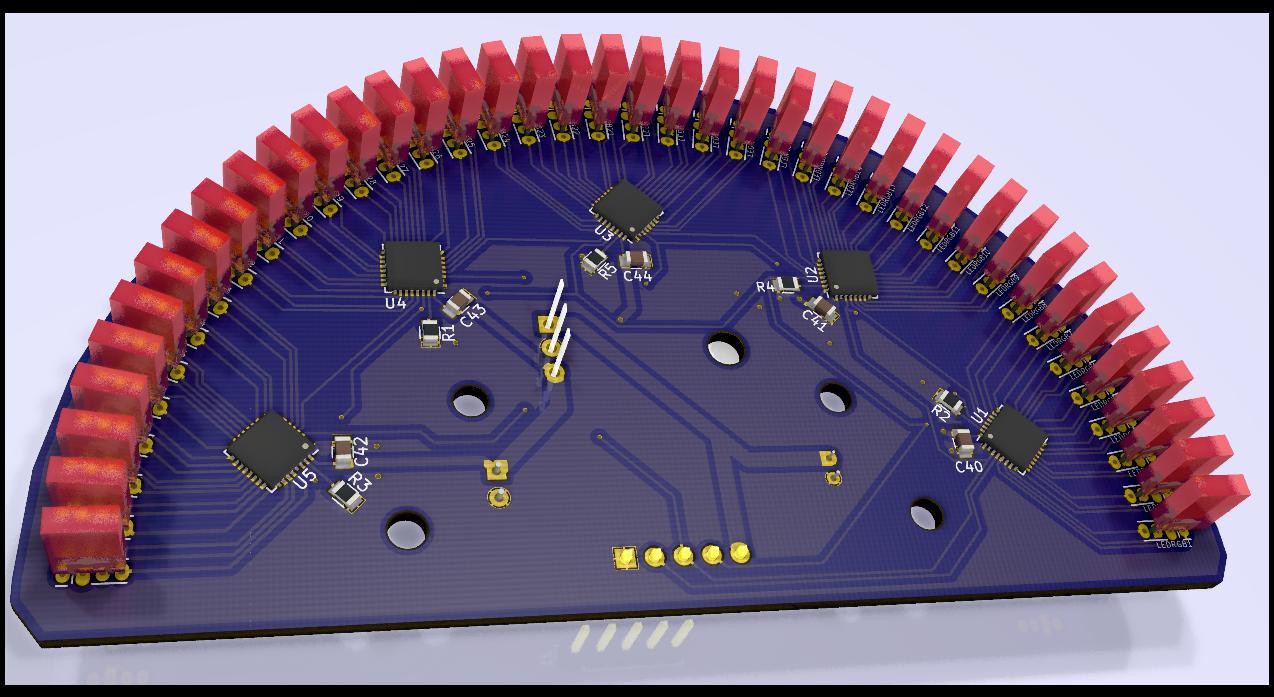
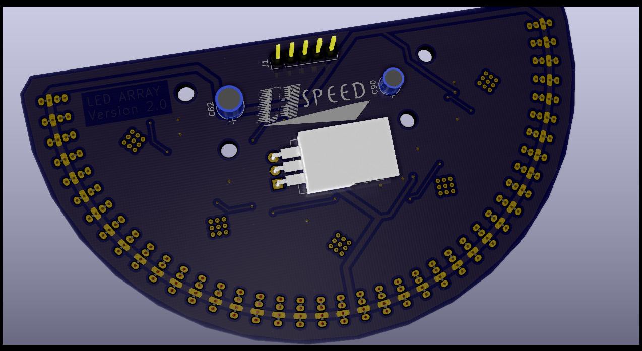
New LED Array ...
05/02/2017 at 17:39 • 0 commentsAnother smallupdate just to show the new LED Array design. This version does away of the 40 ws2811 chips in favour of 5 TLC5947's. This does how ever mean I have to do some hefty rewriting of code to work with the new chips. I dont want to totally rewrite my led code, but I will have to rewrite the adafruit library to work nicely with my current functions...
Anyway heres a little render
![]()
![]()
Im nearly ready to send these new boards off to a fab house to print for me... But I want to do some further research to make sure every things right...
Im not entirely comfortable with the tracks out of the TLC5947s being only .3mm, while all the real energy is send out the LEDs, Im still worried the .3mm might be too little for the grounding off the LEDs... Maybe I got my understanding of electronics totally mixed up :D
-
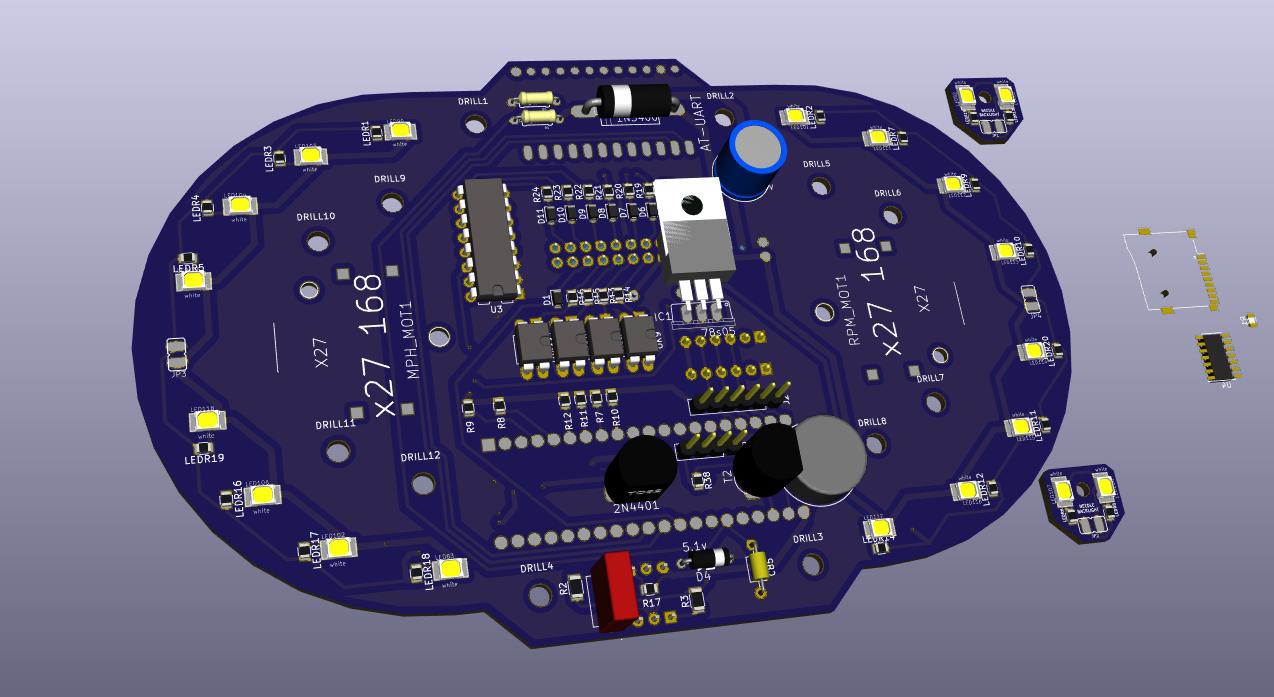
Rev6? Small Update
04/30/2017 at 14:14 • 0 commentsWell ive been doing some researching and redesign work of the main board....
This is a small update as really its just pcb design work and schematic editing, however... Could this be the rev6 board?
![]()
Ive been getting to grips with KiCad, boy was it a learning curve. There are still some things eagle does metter... Arrays for a start... but Once i got round most of KiCads niggles I managed to get some good work done...
So yes this could be Rev6, I want to do some more research before I set this design in stone... This current design allows for both Nextion and EVE displays so the transition can be done using the same board, I have also incorporated the new rpm filter. Made nearly all the resistors SMD... Have a 2x10 socket for an easier less messy cable connection. And also have an alternative way of running the leds.
Some people mentioned that there are multi channel alternatives to ws2811's... And while I might have to create a new library so the code I already have can interface with them, It does seem worth it and would make the led arrays a little cheaper to build, as I would only need 5x tlc5947s to drive all 40 rgb leds... rather than 40 ws2811s...
Im yet to design the new array pcbs and I need to continue having a think about how to go about with the new chips...
Oh and as this quite possibly would be the final circuit design im going to have this version fabbed at a factory...
Anyway wish me luck :)
-
HUGE UPDATE
04/17/2017 at 14:16 • 0 commentsApologies for not keeping people more updated, but as some of you know Ive had some upheavals at home which have made it difficult for me to work on my project as much as I would like… And post updates even less.
While changes to hardware is near impossible at the moment I have used the time I had to do a lot of software work. Ill try and bullet point these changes…
• Corrected fuel gauge and volt meter graphics to match the input data.
• Reworked the menu list changing options available
• Fixed the preview led colours in the colour menu
• Heavily reworked the colour picker menu
• Made the display talk to the MCU and programmed in the menu navigation
• To do this I had to implement a mixture of Nextion library use and Serial talking
• Ive done a lot of recoding of the LED update functions. Including reworking the peak lag spot animations and menu interactive animations.
• You can change colours for the LEDS through the menu system, though currently this doesn’t save, so when power is cut off it returns to the default settings.
• Fixed RPM calculation functions now accurately detects RPM through millisecond readings(this may be turned into a hardware timer interrupt in the next major hardware version…)
• Built the wizard for setting the high and low fuel level readings. However the hardware needs changing as the current design doesn’t work… even though it should![Sad]()
• And other ‘stuff’ I cant even remember right now……. Lots of tweaking….
Ive also gone through a few different versions of RPM signal filter to try and get a working readable signal. This bit really has been a nightmare esp given my current circumstances making it really hard to RnD this bit.
Though ive managed to get it working. I may still do some changes to the rouge filter I got now. Just to guarantee a cleaner signal, but its working…
I nearly gave up on my project because of this… Whats the use of a speedo dash thing if it cant even read the RPM………….
Once Ive totally locked down the filter design Ill add it into the design of the new main PCB, Ill also upload a schematic of the filter so anyone else can use it if they like… Its only fair as I based my working design off a design someone else made elsewhere…
Ive uploaded a video of the update onto youtube… I talk through some of the updates ive done. I warn you its unscripted, not even got bullet points so theres lots of Umms and Uhhs as I try to think of what I need to say.
I hope you like. -
Not dead!
02/20/2017 at 20:18 • 0 commentsWell not got good news I'm afraid, the projects "NOT" dead. Far from it, ive been working a lot on getting the interface to talk properly with the maple. With mixed results.
Some times some serial messages just dont seem to get through and its a real head scratcher.
Normally I would consider some sort of call back and confirm error correction. But to do something like that on the Nextion display is near impossible as its so called programming is very very limited.
Its a puzzle thats for sure. And one which I would solve. If hopefully i have the opportunity...
Sadly its very likely im going to have to put the project on hold for maybe a few months. This is because after family issues, im going to be unavailable to really work on the project that much. This may last a few months. Ill have a clearer image tomorrow. But suffice to say. I'm not in a good place right now.
For those that follow me. Sorry.
This will get done I promise that. But its just going to be a while now.
-
Another little update.............
01/16/2017 at 23:30 • 0 commentsAfter the break over christmas I have finally got round to making the second LED Array module for my project. Its a tweaked layout design of the first (right hand side) ive removed most of the vias, cleaned it up a little... Improved it...
Anyway ill get on with some coding tomorrow. I need to get the real RPM signal reading bits working. I was having trouble with that before. Not sure why....
Digital Speedometer
A new digital dash to replace the slow inaccurate one on my cheap Chinese bike