Mangus Tiranus
-
Rev 4... >.>
11/29/2016 at 23:39 • 0 commentsAs you could see in my last video... Rev 3 didnt go too well. The leds were failing fast...
So I decided to go ahead with the through hole led approach... Trouble is they dont make 3mm domed addressable leds... The smallest addressable leds I could find were 5mm domed. But theyre too big to fit 40 leds in the array.
I can however fit 5mm rectangle leds, but their are no addressable rectangle ones.
If anyone knows where i can find some please let me know as it would save me a whole lot of trouble.
Anyway i now have 5 mm rectangle RGB leds driven by individual ws2811 chips.
I have designed and built the array to be modular and bolt on both sides of the main control board.
This should last the whole prototyping stage now.
I also cut these boards out so theyre more like the final design.
Im still waiting for the controller chips to turn up then I can solder everything on.
i was going to update once I did that but i wanted to put something up on here as i've been a little quiet on here for a few weeks.
-
Umm Rev3 :D
10/22/2016 at 19:26 • 0 commentsSooooooooooooo. Rev 2 had so much promise, but after getting it working I quickly discovered it had some serious issues with power distribution.
So I had to redesign the board and give more thought to the power lanes.
I now have 5v regs dedicated for each of the led arrays and a third 5v reg for the rest of the project.
Because I need a stable regulated 12v to run the backlights and run the fuel sender probe, a friend recommended that i remove the 12v regulator I had because it would be better to use a boost converter from the third 5v supply.
Its a stop gap measure that might change in a later version. But this does solve some issues with the widely ranging 12v line off the bike.
The old 12v reg I was using needed a 2volt + headroom to get a stable 12v. The other option I had was to use a low drop 12v reg. I found one, but they're expensive.
And its also possible that the bikes voltage could end up dropping bellow 12.5v... (the bikes voltage/rectifier is on the blink i think, I will fix that, but it does highlight a possible real world issue the dash has to contend with.
I would like to make this a product I can sell, so while I'm learning how to build it, its good to find these issues and work out how to fix them.
Anyway, I've etched the board and got a solder mask on both sides. I might even put on a silk :D Who knows...
Anyway tomorrow ill be reflowing the SMD bits. Ill post a pic then.
-
The Fall & Rise of Rev 2
10/15/2016 at 16:40 • 0 commentsSo its been a while since I made an update. As always I've been busy behind the scenes, doing lots of head scratching and getting mild concussion from banging my head against the wall :p
So where am I at?
Well I've built the Rev 2 prototype board. YAY, however it really wasn't simple sailing.
Come with me on a journey of frustration and insanity...
I got tired of waiting for the toner transfer paper to come from china. Its still not turned up and I think I might have to log it as an undelivered item in Ebay... So I went ahead and used some magazine paper to do the transfer, and it didnt go quite as nicely as I've seen other peoples transfers go.
While it was better than the baking paper some toner just didnt pass over that well. I think the ink on the magazine paper interfered some what with the heating or mixed into the toner. Not sure.
So I still had to get the sharpie out and fill in some missing or broken bits. But it looked alright and I etched the board. So far so good. A few weak or broken tracks but reenforced them with some solder.
I was going to do a whole solder mask and silk screen layer, but as the solder mask didn't come out as nice as I hoped, i decided not to bother with the silk screen.
I think the issue with the soldermask is I was using a UV torch and it just wasn't strong enough to penetrate into the paint to make it stick to the board correctly. So when I pulled the OHP sheet off it also pulled some of the mask up as well.
Anyway I managed to patch that up and had clean pads for some reflow soldering.
I also got my paste in the post the day after I set the solder mask and was eager to try and solder on the 80 addressable LEDs.
Pasted on and placed the SMD parts, and then I went to a old mini baking oven that was my mums and put it in. I used the reflow chart for the LEDs as a rouge guide knowing the oven wouldn't exactly match it. Hand controlling the temperature dial I preheated and then sent it to the peak temp, and watched through the window to wait for the solder to melt and set.
Well that worked.
I spent the next day drilling all the vias and soldering the rest of the stuff on...
It was time to switch it on. I got my 12v PSU out and wired it in. And turned it on... keeping an eye on the PSU light incase there was a short. (the light normally goes dim if there is)
And nothing.
Nothing turned on, the PSU light was still on so there couldnt have been a short. But then I noticed the jumper wire I was using to power the board was melting and smoking... I quickly pulled the power out of the board before it caught fire.
Turned out there was a short, but because it was on the other side of the 5v regulators my PSU didnt seem to notice.
So the next day i started to look at the board closely. I couldnt find it. I exspected maybe some solder was touching ground where it shouldnt be, or a bad track etch somewhere. I spent hours looking and couldnt find anything.
Using my continuity tester I was able to find that there was certainly a short somewhere from the 5V line, but just couldnt find it anywhere. Then thats when I started to fear the worst. What if some solder paste made contact underneath the many smd LEDs, its certainly possible. If that was the case it would have been a total nightmare to find and fix.
It was at this point a good friend stepped in and suggested a way to isolate where the short was, simply by cutting the power rail traces into segmnts and testing each segment. Starting with the LEDs... Good idea. Easy to repair too.
So I isolated the left array of leds. Nope not there, Thank fluff... Isolated the right array... YAY not there either. So it wasnt underneath the leds. That part of the nightmare was over.
I then managed to Isolate the short to a 1 inch by 2 inch area and I still couldnt find it. Took me a few hours to figure out what 'I did wrong'... My fault entirely.
When the toner didnt transfer quite right I penned on some of the missing tracks and i stupidly got mixed up and penned in a track that wasnt there, I penned a track right from 5v to ground. I mistook a small slither of ground plane for a track from a pin... Stoooopid!
Anyway, I broke the short and fixed the isolation cuts. And powered it up... IT WORKED!
Great.....
I just wish I was ending the post there. Wouldnt that have been nice.
But NOOOoooooo! Something else had to brake.
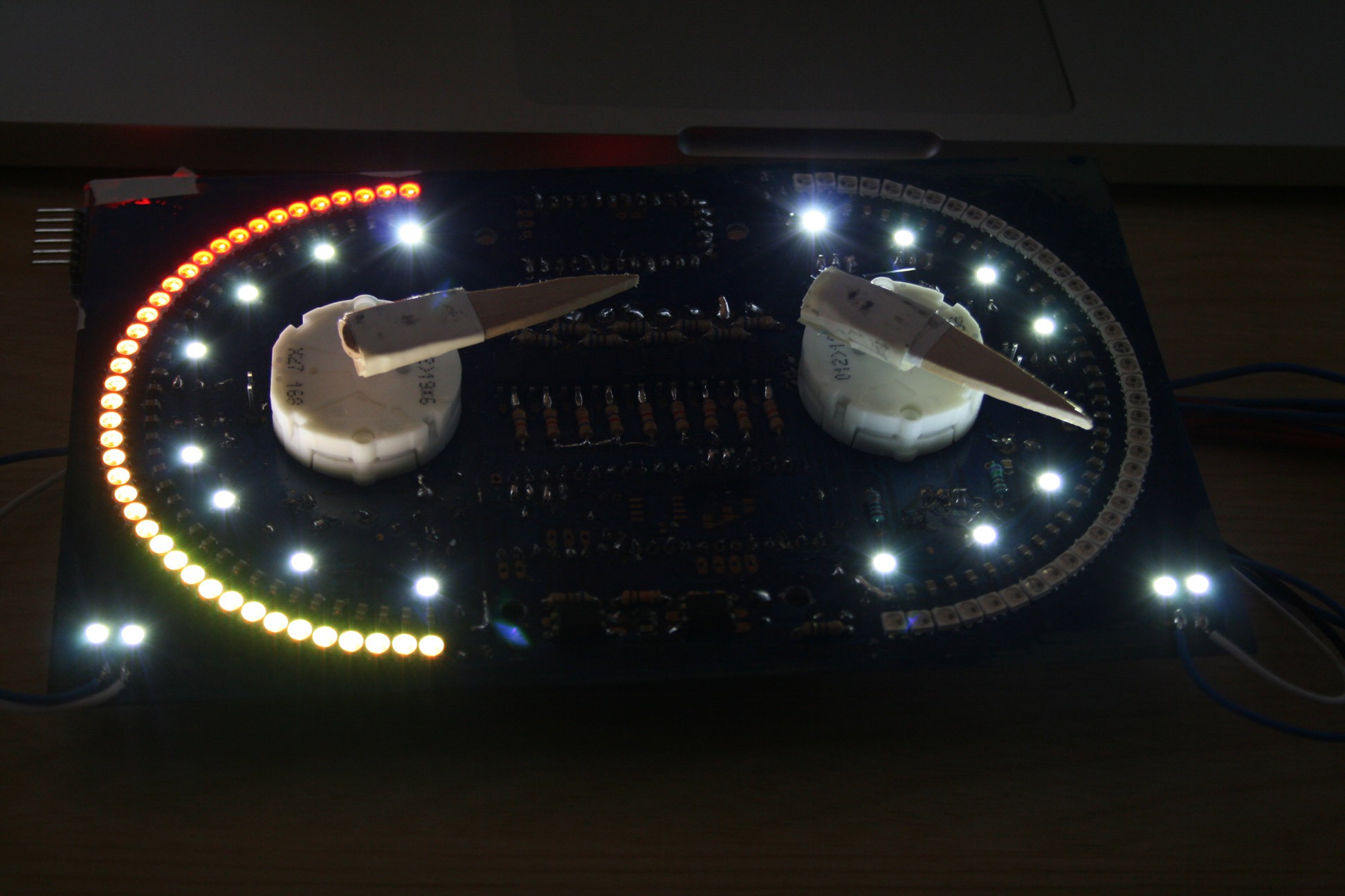
So last night I was tweaking my code to include the extra leds, in the earlyer mock up I was using 18 LEDs, in this prototype Im using 40 in each array. Setting the number of leds to 40 does something odd... it crashes my main MCU, it shouldnt. I can only assume the faslLED library im using that was ported to stm32 is buggy. Trouble is the crash was also locking out the serial connection, so I was struggling to remove the broken sketch and replace it.
Today, I got one of my spare mini maples and soldered up the legs to it and put in the sketch, placed it onto the board and didnt realise it was sitting one pin to the left. Powered on and killed it :( Dead chip. not really sure how as it was only taking 5v in a input pin, but its now dead... Doesn't power up, and if I try the chip just heats up dramatically.
So i got out my last spare. Placed it in correctly. AAAAND... That died too :( no idea why again. Same heating up. May be they came from the same batch of dodgy builds. Or maybe I just broke them :(
But no fun, I've now ordered some more from china, but its going to take weeks for them to turn up.
I can use this time to investigate what went wrong.Anyway heres some pics :)
Sorry for this long long LOOONG post :D
![]()
Oh before I forget to mention, i think the transistor that controls the white backlight LEDs popped. They seem to be stuck on. no code is running them to be on.
![]()
-
MAJOR FAIL!!!!!!! RIP Prototype N.o1 You didnt even have a chance :(
09/29/2016 at 22:13 • 0 commentsI guess it was always going to happen... At least with the first.
I failed... Really failed.........
So with this prototype board I got impatient. I really want to get on with coding the project, but i need a working board to do that.
So instead of waiting for the solder mask paint I went ahead and started soldering bits on. I learnt a lot about the board, things i need to change and fix...
Stupid things like needing to put solder pads on the opposite side of the board to the component... Or wiring the serial connection between MCUs correctly and not having the tracks lead to one pin to the left -.-![Embarassed]() Those I fixed with some bogging... But still this is the prototype board. Its for finding these mistakes and fixing them...
Those I fixed with some bogging... But still this is the prototype board. Its for finding these mistakes and fixing them...
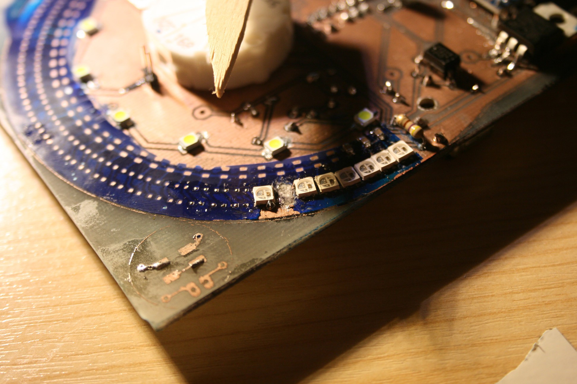
But the final nail in the coffin for the board... After bodging on a solder mask. Ive discovered even with paste, I cant use a soldering iron to solder on the addressable leds. It kills the LED chip really really quickly. When trying to remove one of the dead leds with the iron, it basically ripped up the track and half the fibre board![Sad]()
Live and learn I guess...
Well im going to have to make a new PCB, this time ill fix the tracks and correct the solder pad sides... Ill get a nice solder mask painted on as well before i do anything. And buy extra flux because BOY do i need it. This lead free solder is terrible... Really sticky and turns gloopy very quickly.
Anyway here is the carnage...![]()
![]()
-
Prototype PCB!!!!!!!
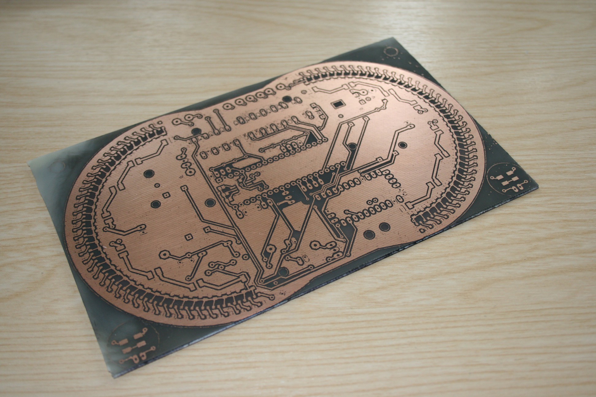
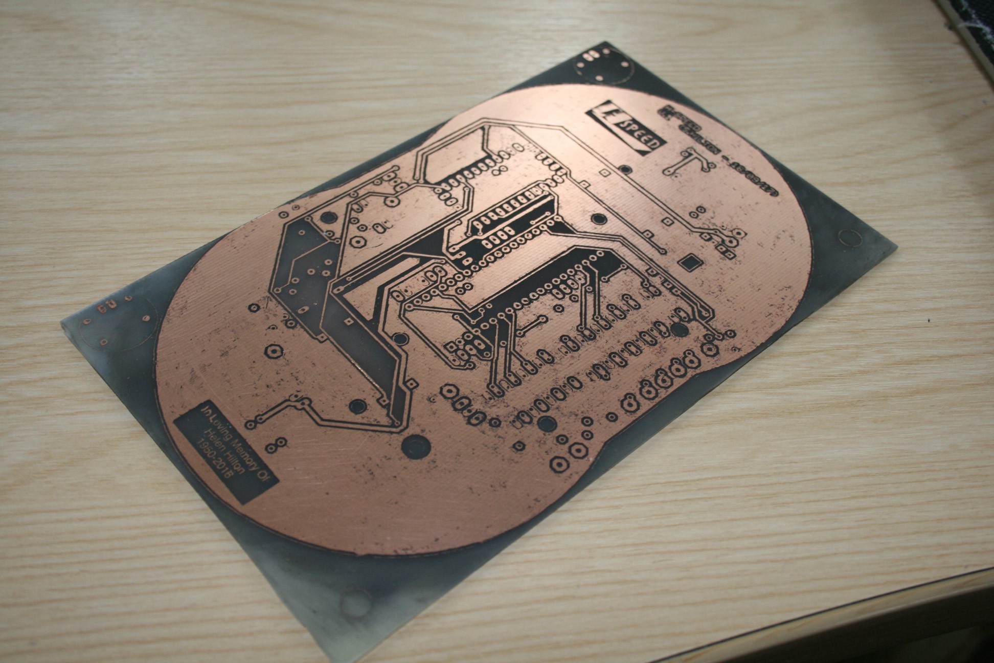
09/22/2016 at 14:52 • 0 commentsSo last night I etched my first PCB is about 20 years.... scary...
Its not gone perfect.y, I used the toner transfer method on some baking paper. But toner cracked and flaked a bit and didnt iron on perfectly... So its a little messy and one or two traces might be broken, I can fix those with some solder.
But its a functioning board so should work for the prototype.
When I make the final build of this version of dash ill make a cleaner board.
Anyway heres a couple of pics of the thing.
![]()
![]()
-
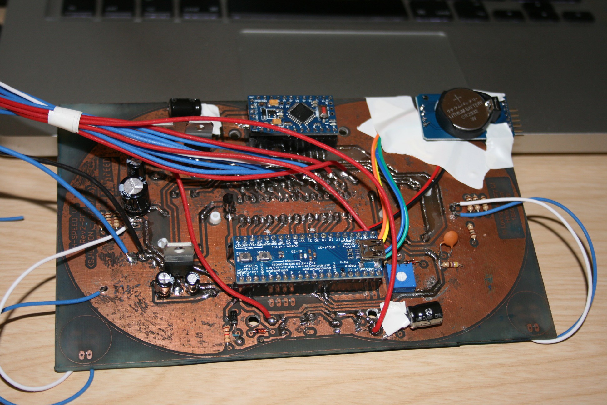
Could do with a few sets of eyes, my wiring schematic
09/03/2016 at 10:21 • 0 commentsSo I've reached the stage in my project that my skills are at their weakest... Electronics! Funny that, this being a electronics hacking/making site >.> ...
I've put together this schematic based from various sources of how toos and i really need some proof reading before I order in all the parts and build this on the breadboard.
I'm pretty certain I've made mistakes, got some values wrong or implemented the wrong type of circuit for the task...
One issue I have with my bike is its mains voltage is anywhere between 12 and 15 volts. So I need the various 12v lines in off the bikes wiring loom to be able to handle that variable.
I have a 12-5v module for powering the project that can handle that (purple thing), just bellow that is the jumper for the 12v mains in, and 2 voltage test circuits. One for testing the mains voltage and one for testing the fuel level. Looping the 12v back down the FUEL_Y wire (yellow wire) and reading the voltage off the FUEL_B (blue wire) that comes back. In the tank there is a float on an arm thats attached to some kind of variable resistor. At this stage I have no reason to assume the voltage going into the variable resistor in the tank is anything other than the 12v mains off the bike. (other than 12v being a nice high tank exploding voltage if the resistor failed :D ) Though I will look that up more and confirm that its possible I guess that the gauge on the bikes original dash dropped the voltage level before sending it back, I will test this...
On the Adrafruit powering neo pixel guide, it says to use 1000uf caps to stop any voltage spikes coming up the line. I ordered some and theyre pretty big... I may have also ordered the wrong type, being electrolytic. These are about 1cm in diameter and 1.5 cm long... Are there any smaller package options I could use?
Im using opto isolators for many of the inputs from the bike. This to protect the IC from any spikes...
But I'm a little unsure if I've got the circuit right for them.
The RPM in, I'm using a resistor to drop the voltage as I dont want to interfere with the signal. At the moment I believe the signal is 12v (bike mains voltage level) pulsing. Im going to confirm this once I get an oscilloscope. Would a voltage regulator interfere with the signal? Smooth it out?
And If using a resistor is the right thing to do what value should I give it? Given the wide variable the bikes voltage is...
On the left of the maple mini are some other inputs.
I have the Running Headlights and High Beam going through a regulator, as they will be turned on for long lengths of time.
The indicators are on 630 ohm resistors are they just flash, I dont think heat should be an issue there?
Will the voltage regulators have a heat issue? Do I need to think up some sort of heat dissipation into my design?
And finally, pay little attention to the gear number inputs... Im not entirely sure how Im going to handle them at this point, my bike only detects neutral, Ill have to change the switch for that to work, and If i do, would I run it through the loom or just send a signal down from the dash unit... Again at the moment these are using 7805 regulators...
I also have a space issue with the 7805 regulators... having this many takes up a lot of pcb space. Even to the point of me thinking about making a second PCB board. I much rather keep this all on one.
Anyway, anyone please take a look over the schematic and tell me if you see any real issues with it, and if you think my resistor values are wrong :)
Thanks in advance :D
![]()
-
RIP Pin12, you will be missed.
08/29/2016 at 17:51 • 0 commentsSo it seems yesterdays RPM failed test was not without its casualties...
The 12-5v module is dead :( RIP as is pin12 on the maple mini... :(
Its a good thing I have 4 more Maple Minis... and 3 more 12-5v modules...
To be honest I think its pretty impressive I've not managed to kill the entire board if not more pins this far down the development... So I think 1 pin so far isn't too bad :P
Ill replace the board when i do the final build. Or until I run out of spare pins to burn :p
Its a good thing these things only cost a couple of quid each.
Though this does continue to raise the question. How am I going to read the RPM signal.
I was using a MOSFET transistor to switch the 12 to a 5 signal. (I may have had the pins mixed up on it, not sure) I guess I'm going to need some kind of protection circuit. Trouble is I'm not an electronics engineer by trade, so I dont know how to make one off the top of my head. Time for more reading.PS I'm happy to take suggestions if you have ideas how to fix certain problems I will come across.
-
Quite possibly may have killed my bike D:
08/28/2016 at 13:39 • 0 commentsWas going to test the RPM signal on the dash to see if the transistor diodes worked and if my code worked to the real RPM signal...
I wired and checked the 12V-5V regulator. Tested that and it was sending out a nice clean 5V signal for the dash. I turned off the bike to wire in the dash and then do a voltage check on RPM signal... But I smelt the magic smoke... I pulled out the regulator thinking I might have killed that. Smelt fine. Then I tried to turn on the bike again, nothing. I pulled out my tester and 0.3v... 0.2... 0.1........ dead. I think I may have killed the electrics on my bike... I need to do some investigating to see whats actually died. It might just be a fuse. But Im worried its something more expensive :(
Im not sure how it happened. It must have been the croc clips connected to the - pin in the multi plug. It might have shorted to another pin.
Ill let you know.... *cries*
UPDATE, was just the fuse... Still I wonder why it popped :(
-
Update to the LED side of things
08/27/2016 at 16:31 • 0 commentsNew update, spent the last couple of days rewriting only 40 lines of code...
Ive added a peak lag to the leds as well as a indicator animation...
I want to see if I can clean up the code or make it a little more efficient as its a bit of a mess at the moment. But it does work :)
Digital Speedometer
A new digital dash to replace the slow inaccurate one on my cheap Chinese bike