 charliex
-
Setting up Eagle and beginning a design.
08/28/2016 at 20:18 • 0 commentsSo far I've gone for the STM32F446VET6 a LQFP100 Cortex M4, I switched away from the LQFP64 because I wanted the option of using the FMC for external RAM, probably muxed PSRAM.
I use Eagle for these type of layouts, and I don't have a part already for this chip, so time to make one, I have older videos on YouTube showing a video of the BSDL, but this time i'm going to do it a bit differently and use a new service I recently came across.
I'm going to create the part from a BSDL file, which is at BSDL for STM32F446 a BSDL file is a Boundary Scan Description Language file, unzip this file to a folder somewhere.
Load Eagle, create or add to a new library, run the ULP make-symbol-device-package-bsdl.ulp
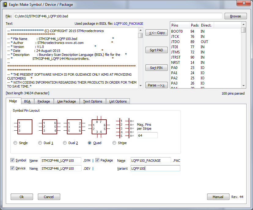
Load the LQFP_100 BSDL file for the STMF446.
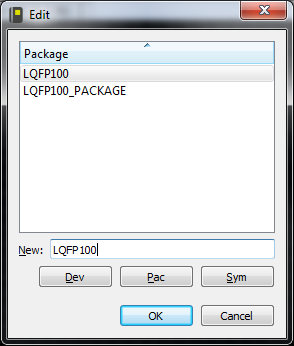
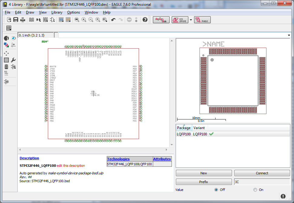
I selected quad, so that will be the symbol layout as it'll appear inside the Eagle schematic editor. I also added a Variant name as LQFP100![]()
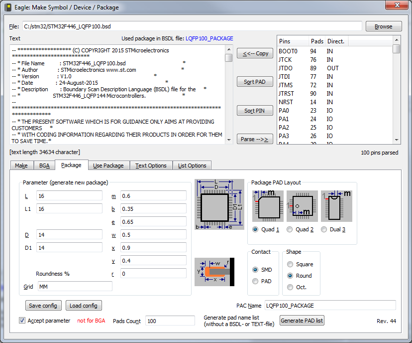
Next go to the Package tab, chose the layout. The Parameters are in the STM32F446s datasheet in the mechanical selection, most of the parameters will be listed in a table. Copy them over and select the style of package, save config and accept parameter
![]()
Go back to the Make Page and click Ok in the bottom left.
This will appear
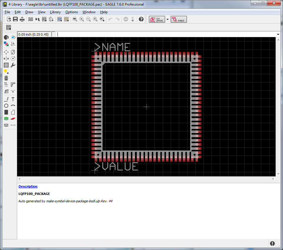
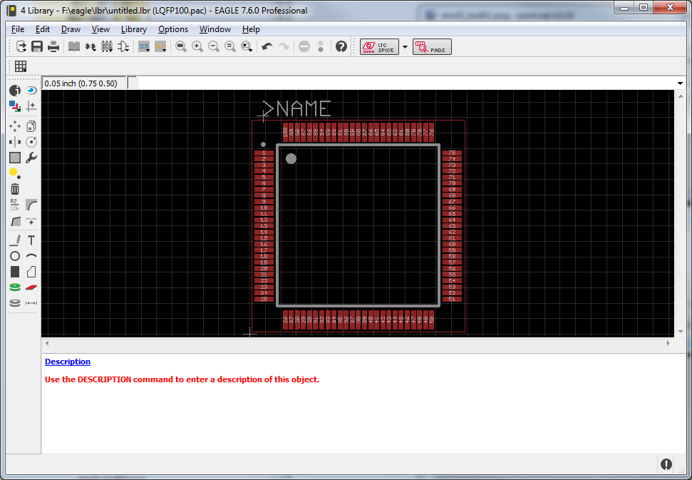
Quad style layout with pins on all sides, some people prefer to split it up into groups, you can edit this in the Symbol editor.![]()
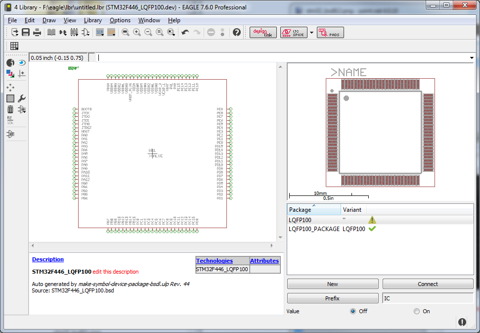
But for now under Package on the middle right, right click on the LQFP100_PACKAGE and select Edit Package.
Note that the pins are overlapping the information entered in the BSDL conversion wasn't done correctly. So now you can either move all the pins around to the right place, redo the import, use an existing layout and copy that it in...![]()
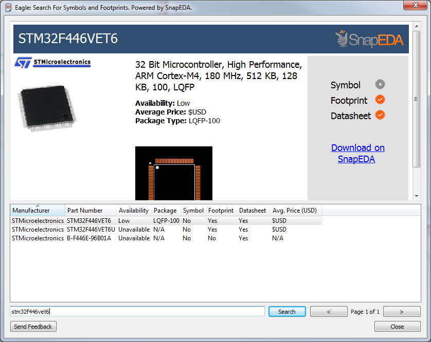
Or you can use SnapEDA to find the package and add it, I happen to know already that SnapEDA doesn't have this symbol in Eagle yet, but it does have a LQFP100 14x14 footprint. Otherwise we could have just gotten it from there in the first place.
If you haven't already make a SnapEDA account, and setup Eagle to use it.
Login to SnapEDA and go here Eagle Plugin, follow the instructions which is basically copy the all the files except the icon to the eagle ULP folder and the png to the eagle bin folder. Open the eagle.scr file (in the scr folder) and add in to the SCH/BRD sections
     '[snapeda.png] SnapEDA : Run snapeda.ulp;'\

so it looks like


BRD:
MENU '[designlink.png] Search and order : Run designlink-order.ulp -general;'\
     '[pcb-service.png] PCB Service : Run pcb-service.ulp;'\
     '[idf-3d.png] Export to IDF 3D format: Run eagleidfexporter.ulp;'\
     '[snapeda.png] SnapEDA : Run snapeda.ulp;'\
;

SCH:
Grid Default;
Change Width 0.006in;
MENU '[designlink.png] Search and order {\
                                          General : Run designlink-order.ulp -general; |\
                                          Schematic : Run designlink-order.ulp; \
                                          }'\
     '[LTspice.png] LT Spice simulation {\
                    Export: RUN ltspice.ulp /E; |\
                    Export Setup: RUN ltspice.ulp /E /S; |\
                    Export Group: RUN ltspice.ulp /E /G; |\
                    Import: RUN ltspice.ulp /I; \
     }' \
     '[snapeda.png] SnapEDA : Run snapeda.ulp;'\
;
Start Eagle again, and create a new schematic.
At the top of the eagle sch/brd editor you should see a SnapEDA logo, click it.
![]()
In the lower text entry, type in the part number you want. stm32f446vet6 and hit Search.
Select the correct entry and then click on "Download on SnapEDA", you can also do this on their website. It'll open the browser.
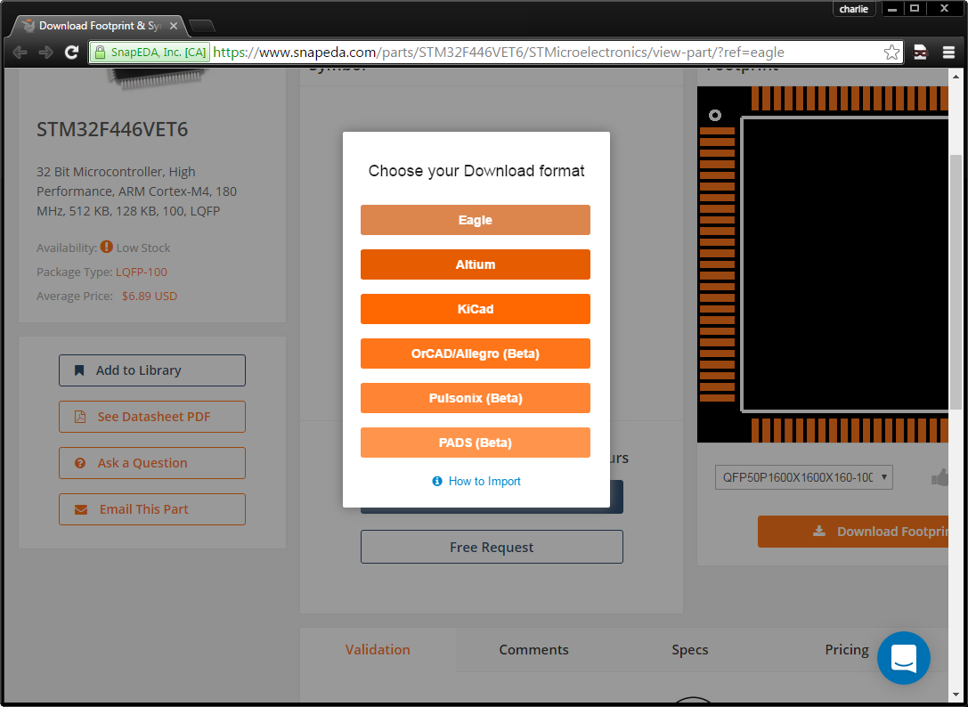
This will take you here, and currently it just shows the footprint, which is all we need at the moment![]()
![]()
Download footprint, select Eagle
![]()
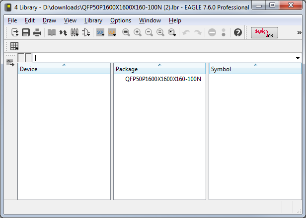
SnapEDA will now download a lbr file for you. the procedure is documented here
https://www.snapeda.com/about/import/
Load the newly downloaded .lbr into Eagle.
![]()
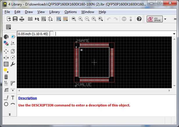
Double click the package listed under Package, the QFP50xxxxx etc
![]()
Now we have a much better package layout, so lets grab it and move it into the library we created with the BSDL earlier.
Use the group, command, i usually just type group<enter> into the eagle cmd line, drag select with the mouse the whole package and use cut(again i type cut into the eagle cmd line) , right click and select "Group: cut" the whole package is now in the cut buffer.
Go back to the BSDL created library with the bad package, without exiting Eagle.
Go back to the Device screen by selecting the LQFP100 device.
From the Eagle menu bar select Library, Package and make a new Package that's called LQFP100
![]()
Now paste the Package (ctrl +v) and click to place it. Remember not to leave Eagle after you did the group/cut on the lbr downloaded from SnapEDA, otherwise there will be nothing to paste.
If you don't have anything to paste, reload the .lbr downloaded from SnapEDA and do the cut again. "group, drag select and type cut, right click, select "group: cut" from the popup menu".
Once it looks like the following,
![]()
Again go back to the device screen, and right click under Package then select New.,, or click the New Button.
Give it a new variant name that doesn't already exist.
![]()
It should be a different variant name from the one that is already there, you can rename the existing one to LQFP100_BAD or something before you create the new variant, don't delete the bad package yet. I Ended up just calling it LQFP100, not LQFP100_CORRECT, sorry about that. So look for LQFP100 after this.
You should have something like this, the yellow exclamation means the pins haven't been connected yet. So we will do that next.
![]()
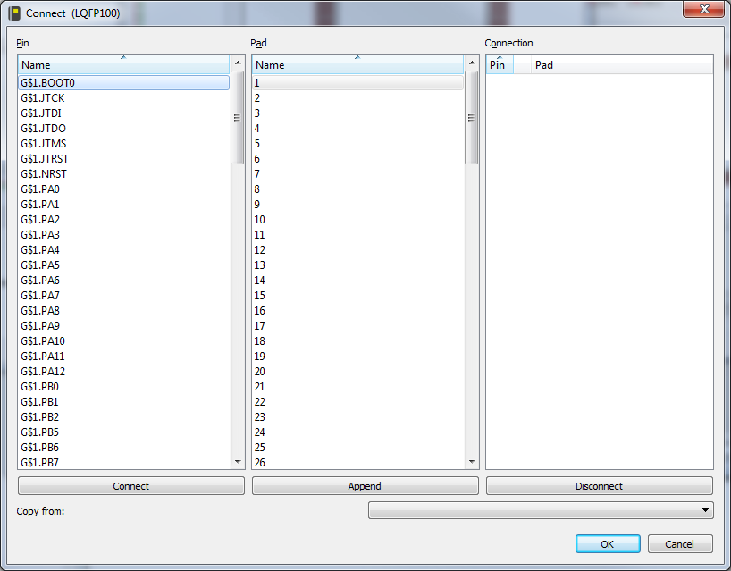
Click Connect, or right click on the LQFP100 (the one with the yellow exclamation mark) variant in the Package list
![]()
Now we'd normally tediously go through each of these and make sure each Pin was connected to the right Pad, however the BSDL script already did that for us in the bad Pad layout of LQFP100_PACKAGE variant. So Where it says "Copy from" select the drop down and choose the existing variant.
![]()
And all the Connections will be made for you. Now click OK
Now delete the bad Package Variant, right click on the LQFP100_PACKAGE and hit Delete
Now you should have this
![]()
Now all you have to do is give it a useful description , click on the Blue Description line and you can add as much info as you want, data sheet link etc. It uses HTML
<B>STM446VET6<P>

<A HREF="http://www.st.com/content/st_com/en/products/microcontrollers/stm32-32-bit-arm-cortex-mcus/stm32f4-series/stm32f446/stm32f446ve.html">Data Sheet</A>

<p>Core: ARM® 32-bit Cortex®-M4 CPU with FPU, Adaptive real-time accelerator (ART Accelerator™) allowing 0-wait state execution from Fl ash memory, frequency up to 180 MHz, MPU, 225 DMIPS/1.25 DMIPS/MHz (Dhrystone 2.1), and DSP instructions
Memories<p>
Something like that, save the library and you're ready to add it to your schematic.Of course you should print out the pads, check the sizes and depending if you want to do reflow or hand solder etc adjust them etc. Make sure the Pin names match as the OEM sometimes makes mistakes in the BSDL files.
That is it for now, next we'll look at using some of the PCB Assembly services and how to go about minimising the costs involved by using as many of their predefined parts as possible.
-
Setting up the development enviroment
08/26/2016 at 18:47 • 0 commentsThis year we're switching to the STM32 CPU, we've used the PSOC4 for the last couple of years and it has been great, but the STM32 offers a few things Cypress doesn't yet and the most important one for LayerOne peeps is OSX/Linux support. PSOC and STM32 are my go to chips usually.
I'm using the nucleo F446RE as the dev board at the moment. F446RE with the mbed online compiler which is pretty good, it'll also export to IAR/Keil/STM32 tools and GCC via mbed-cli
The compiler is here developer.mbed.org create or use an existing account and add the F446RE to your profile.
FIrst things is setting up the tools, plug it in and grab the latest drivers.
At this time, board drivers are here stsw-link0009
Also grab stsw-link0004 st-link tool
Install everything, you can compile and upload via a a file system with the Nucleo board.
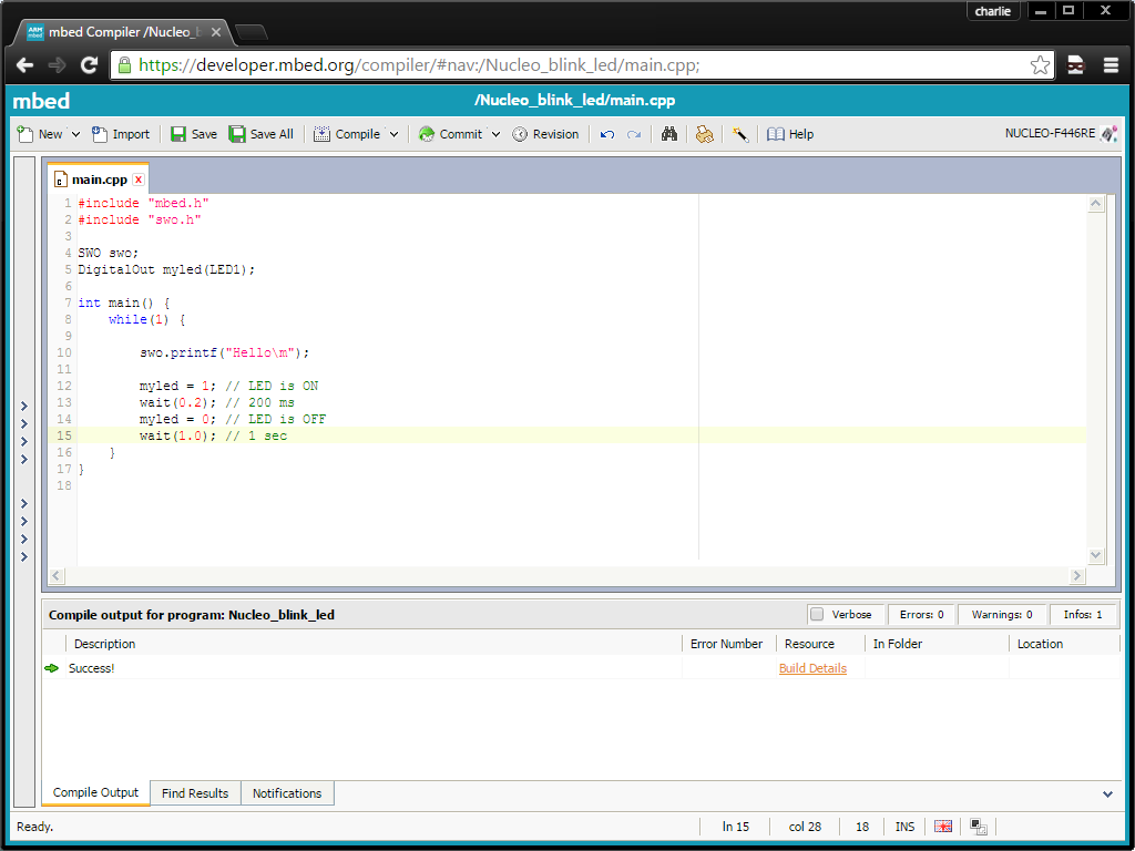
There is an STM32 Nucleo example to blink the led import that into the compiler ,compile it,and copy the .bin file to the Nucleo's mounted drive or via st-link.
#include "mbed.h"

DigitalOut myled(LED1);

int main() {
    while(1) {
        myled = 1; // LED is ON
        wait(0.2); // 200 ms
        myled = 0; // LED is OFF
        wait(1.0); // 1 sec
    }
}
I wasn't able to get uart/usb tx/rx serial working, but i'd rather use the SWO interface anyway. Import the SWO project into your project and add (you can either click on the SWO link and import it, or right click on your project and "Import Library" from "From Import Wizard ..." and type SWO in the search and double click on the SWO from Wim Huiskamp
#include "swo.h" SWO swo; .... { swo.printf("Hello World\n"); }#include "mbed.h" #include "swo.h" SWO swo; DigitalOut myled(LED1); int main() { while(1) { swo.printf("Hello\n"); myled = 1; // LED is ON wait(0.2); // 200 ms myled = 0; // LED is OFF wait(1.0); // 1 sec } }![]()
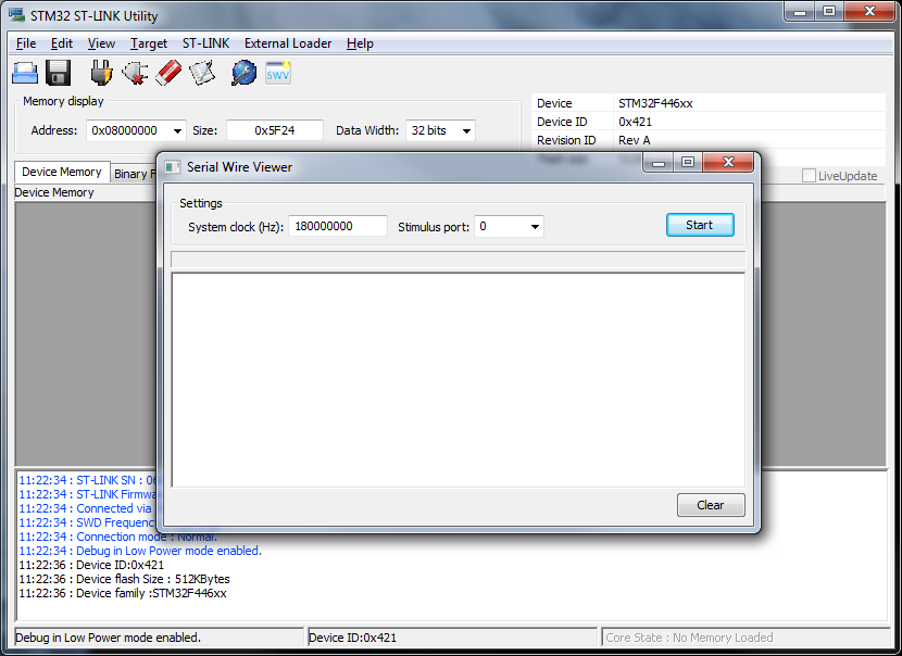
Load ST-link, under ST-LINK, select printf via SWO viewer, system clock as 180000000 (or whatever your clock is set too) and stimulus port 0
Hit "Start"
![]() You should be able to see swo.printf's appear here now. Stop it before uploading new .bin's, it'll self cancel if you forget.
You should be able to see swo.printf's appear here now. Stop it before uploading new .bin's, it'll self cancel if you forget.Test code for SWO is here SWO test
Now you've got a compiler, dev kit and a way to do printf debugging , the st-link v2 hardware built into the dev kit supports debugging via Keil and IAR as well.
At LayerOne we'll be supplying lots of ST-Link V2 USB programnmers as well for the badge, unless we decide to put one on the board itself. Probably a serial bootloader too. Adding the ST-Link to the board does mean another CPU and a bunch of jelly beans.
So we know the chip is very likely going to be the STM32F446RE , next options are Display, RAM, CAN, SDCARD and so on. For CAN transceivers we're using the MCP2551. Currently I'm using an ILI9341 display driver for testing, but nothing settled yet.


 You should be able to see swo.printf's appear here now. Stop it before uploading new .bin's, it'll self cancel if you forget.