I apologize for the lack of build logs. I will be uploading them more frequently, as I have progressed significantly in terms of firmware & software for this project.
Github repo for the (beta) version of the OpenLD firmware here!
Apologies of the rogue assembly codes in the firmware. The readability of the entire firmware will be improved in the future, I promise.
General Overview of the Firmware

In the STM32F4, we need to enable the required peripherals in order to use them. Therefore, the program starts out by enabling GPIO, SPI (for ADS1299), UART (for the Bluetooth module), and Interrupts. Also, it sets up the configuration registers for ADS1299, which is described below. The program then goes into an infinite loop and relies on interrupts for the rest.
The firmware has 3 concurrent interrupts. The interrupt EXTI9_5_IRQHandler, which is activated by the ADS1299 DRDY signal (pg. 8-9), reads data 250 samples per second from the ADS1299. This data is saved in a buffer.
Meanwhile, interrupt EXTI0_IRQHandler is triggered when 250 samples are received in the buffer, hence every second, and sends it to the RN42 through UART for Bluetooth transfer. Since the update rate is not a huge issue, I have opted for 1-second packet transfers for simplicity.
There is also another interrupt for SETTINGS() option, which presents a command line-like interface that is used for enabling & configuring channels. This interrupt is triggered by sending a 'S' character.
ADS1299 EEG IC from Texas Instruments
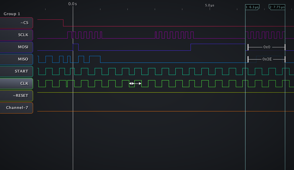
WHOAMI signal from ADS1299 (ID Control Register), captured from the SPI bus with a logic analyzer
The ADS1299 is an all-in-one chip for EEG data acquisition, which makes the hardware much simpler (no need to worry about amplifiers and DRL!). After reading through the 65 page long datasheet, I came to the following conclusion for the configuration (I highly recommend going through the datasheet yourself, as it is fairly involved):- Data sampling rate of 250 samples per second: Since sampling rate for sleep brainwave analysis is not critical, the ADS1299 rate was set to its default, the minimum value. This also helps to conserve data bandwidth for the Bluetooth connection.
- PGA gain of 24: According to the datasheet (pg. 7), highest signal to noise ratio can be achieved by setting the PGA (Programmable Gain Amplifier) to the highest (24x) gain. Although this means higher power consumption, the lower noise floor improves the quality of the EEG data.
- Bias Electrode: Also traditionally known as DRL (Driven Right Leg), it is a source that inverts the average signal of all 8 channels and drives it back to the body. It significantly helps to improve CMRR of the EEG amplifiers.
- Reference Electrode: EEG recordings are differential, hence they need 2 electrodes to obtain a signal. The input SRB1 is used in the ADS1299, which allows the negative input of all 8 amplifiers to be connected to a single electrode. Refer to pg. 17 for more information.
In the Github repo above, the function ads1299_init() in the file cmd_ADS1299.c initializes the features described above.
I apologize for this rough explanation. This is just a beginning of the software side of OpenLD. Now, things are going to get much more interesting. Next time, we'll be evaluating the performance of the OpenLD.
Discussions
Become a Hackaday.io Member
Create an account to leave a comment. Already have an account? Log In.