 Julien
First step was to find proper pinout from the small 40 pin cable of the LP089WS1. I initially wanted to reuse the original cable, cut and solder it to a prototype board. Unfortunaly these connectors are very fragile and soldering one side actually desolder the other ...
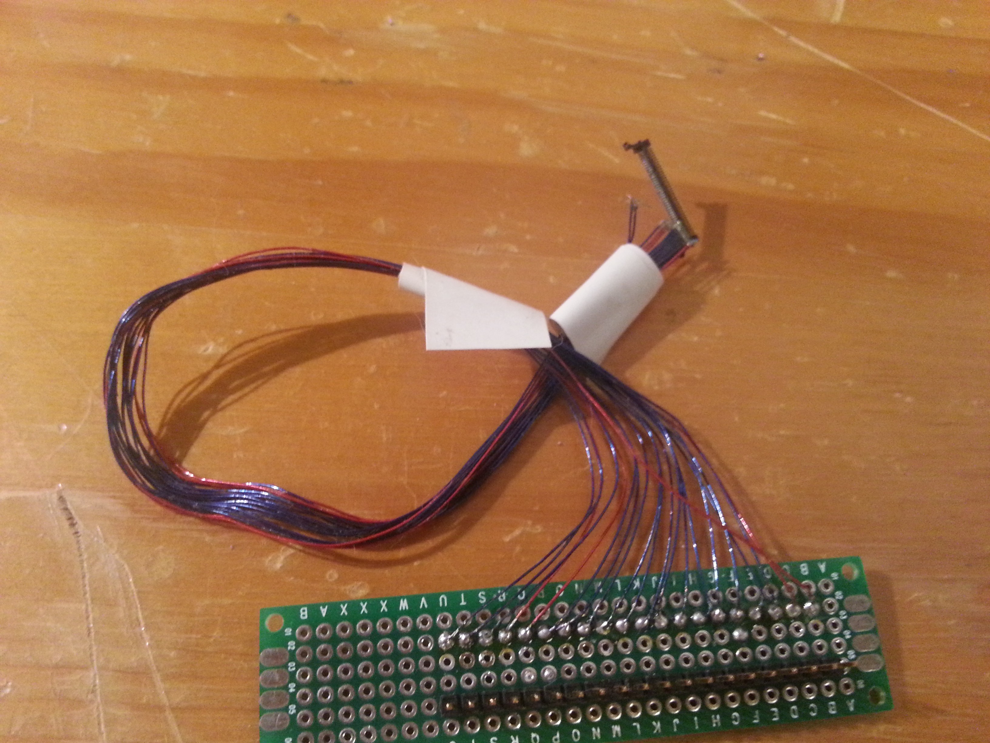
So I choose to buy an already made cable from ebay. It appears that each LCD panel has his own pinout schema : you can't use any cable, you must choose one for your panel. LVDS is only a 4 differencial signal (8 pin), other signal are some GND and Vcc for LEDs and panel - randomly assigned accross the 40 pins by manufacturer. Ebay sellers provide cable with only 12 to 16 output to interface with.
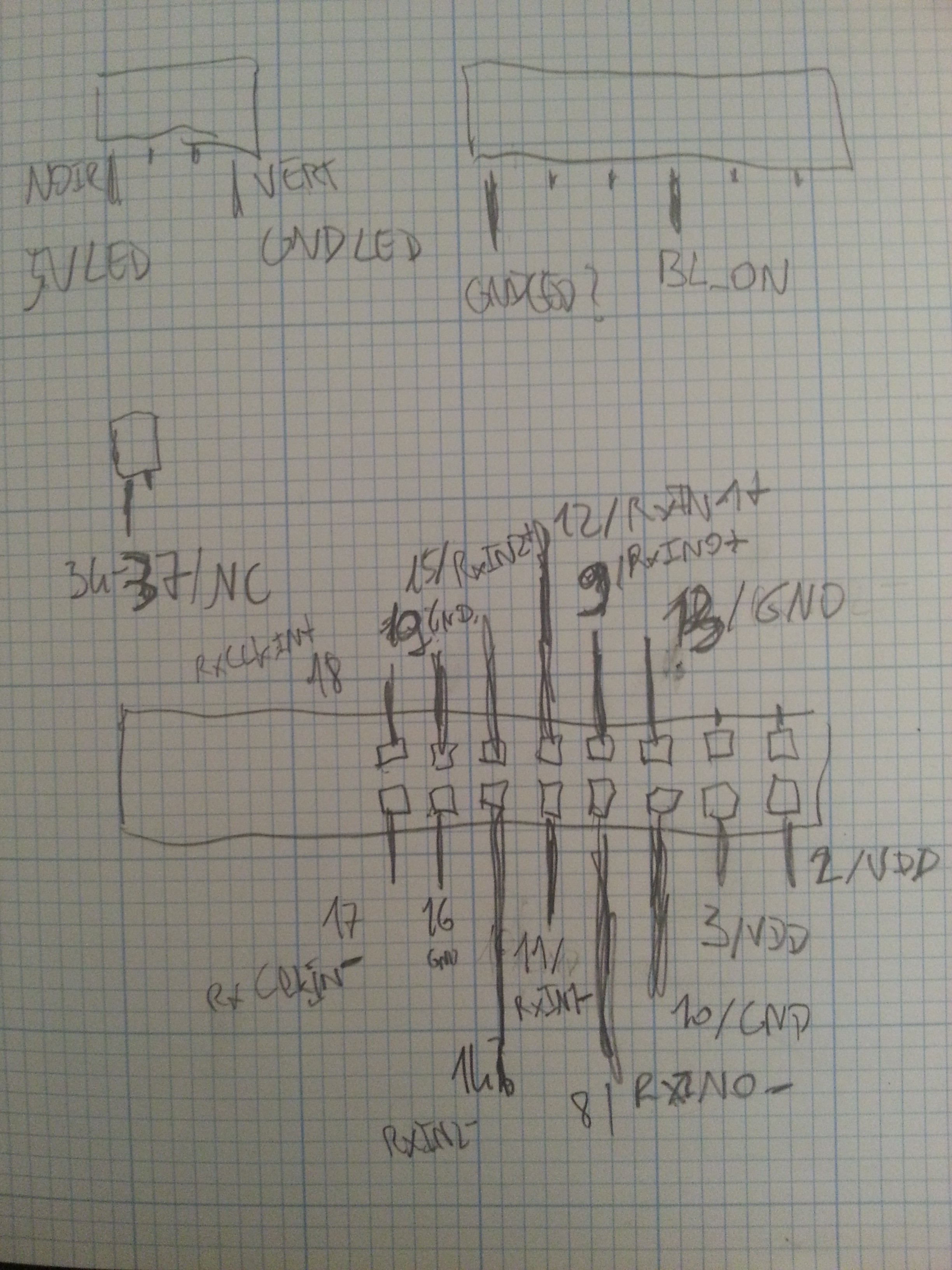
Once received, I imagined that the seller will give me the pinout schematics, unfortunaly he do not know more than me about that. I needed to check every pin with the panel datasheet to figure it (checked twice).
Before going further with data signal and FPGA stuff, I tested the LED with 5V as stated by the datasheet (at this point I was'nt sure the panel was still working).
Actually I needed to supply the panel (3V3) the LED enable pin and LEDs supply itself. And it worked ! A nice shiny dark gray.
Discussions
Become a Hackaday.io Member
Create an account to leave a comment. Already have an account? Log In.