 Tim Wilkinson
This project's been a bit quiet while I waited for the new PCBs to turn up; and they did this week.
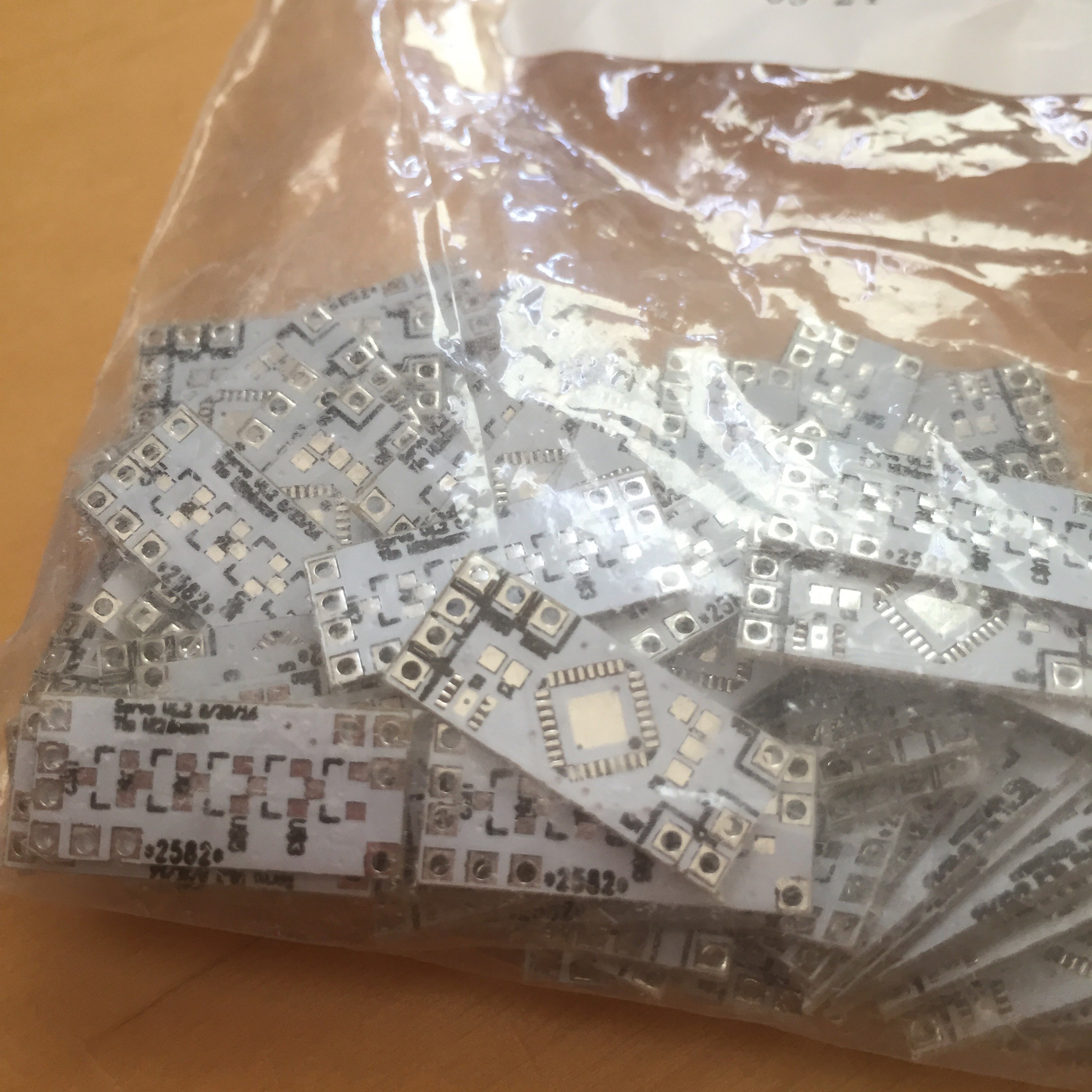
This version has a few improvements over the original:
- No pull-up resistor! Having a pull-up on reset annoyed me in the original design. This version attaches the reset pin to another input pin which, in software, will be set to input+pullup, so pulling up the reset. I left the pads in for the original resistor just in case this doesn't work. There's obvious a window between the board resetting and the pins being configured, but the nature of the gate transistors means this should be okay.
- Extra decoupling. I added pads for an extra decoupling capacitor. I've not seen a need for it, but it does no harm to have them.
- 5 hall-effect sensors. This board has pads for 5 hall effect sensors on the back; the original only had 2. This will give me finer control over the position of the actuator.
I intend to print and solder up a new joint later this week.
Discussions
Become a Hackaday.io Member
Create an account to leave a comment. Already have an account? Log In.