I've finally cleared some time and have been really motivated to get this project moving along lately. Yesterday I printed a bracket for one of the motors with the hope of starting to work out some of the hardware while getting the PS in order. I'd did though accidentally print a NEMA17 instead of a NEMA23. Derp.
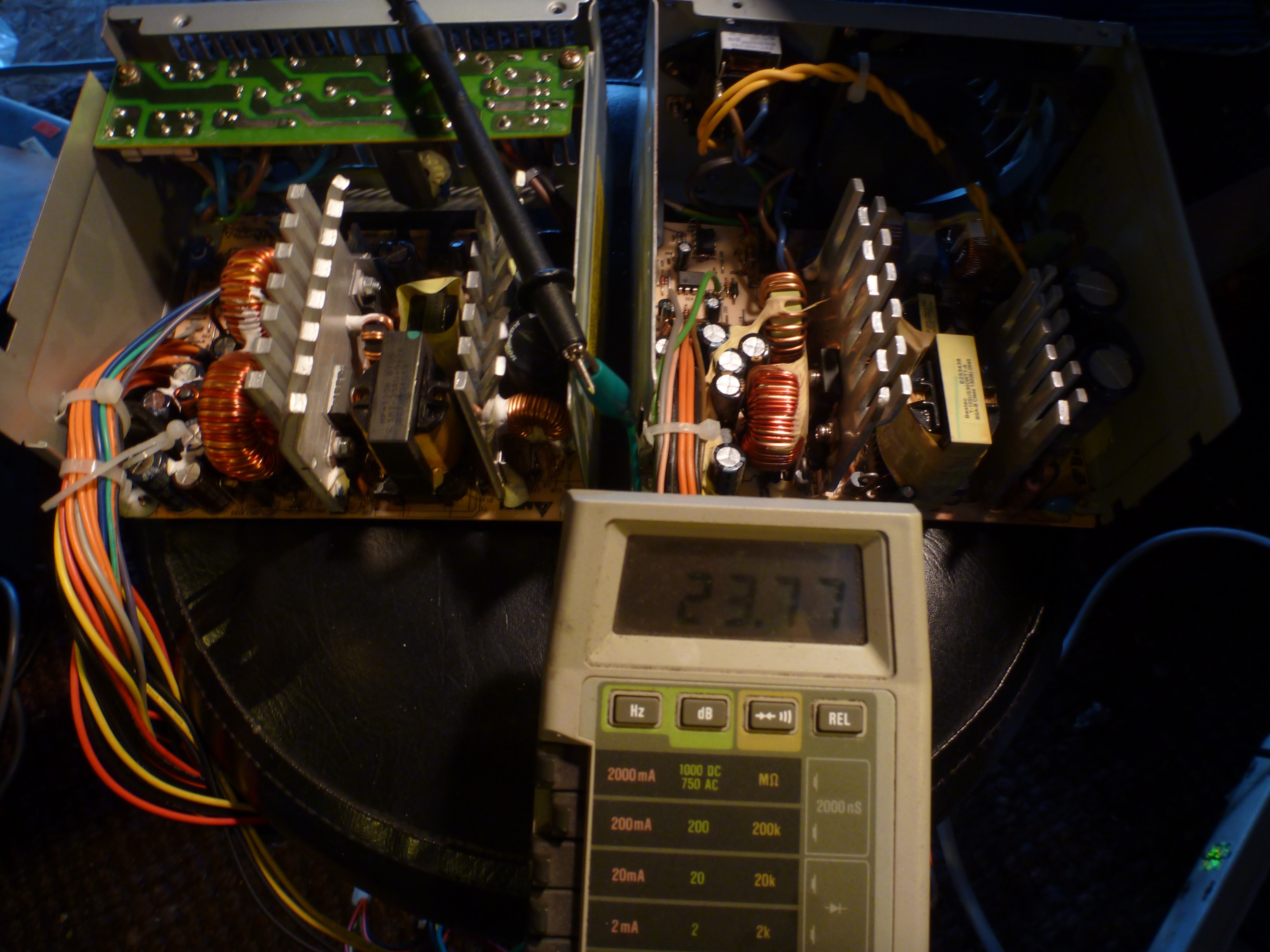
Regardless of this minor setback I decided to get started on the PS today and with only about 30 minutes in I have 24v out! The instructions posted in the links were a perfect explanation on what needs to be done. Only difference I noticed was I didn't need a resistor across pins 14/15 but rather just bridging worked.

While this is showing the highest output of ~24v that will be used for the motors, I also get 5v (for running the micro) and 12v (not sure if I'll use) from the first supply in the chain. And the second supply gives a not very useful 17v on the original 5v line.
Next step will be building up a case for this and printing the correct mounting brackets. I'll also be waiting on several parts. So far I need at least the 7W2 connectors for the Animatics motors and shaft connectors.
 morgan
Discussions
Become a Hackaday.io Member
Create an account to leave a comment. Already have an account? Log In.
It should be noted the voltage displayed in the image is likely to be incorrect. My old multimeter is in need of service and the voltage functions have been suspect lately.
Are you sure? yes | no