Pierros Papadeas
-
Electronics Board v1.1 and PSU
09/20/2014 at 13:31 • 1 commentIt was time for us to test out the designs for our PCB that would take care of the motor control.
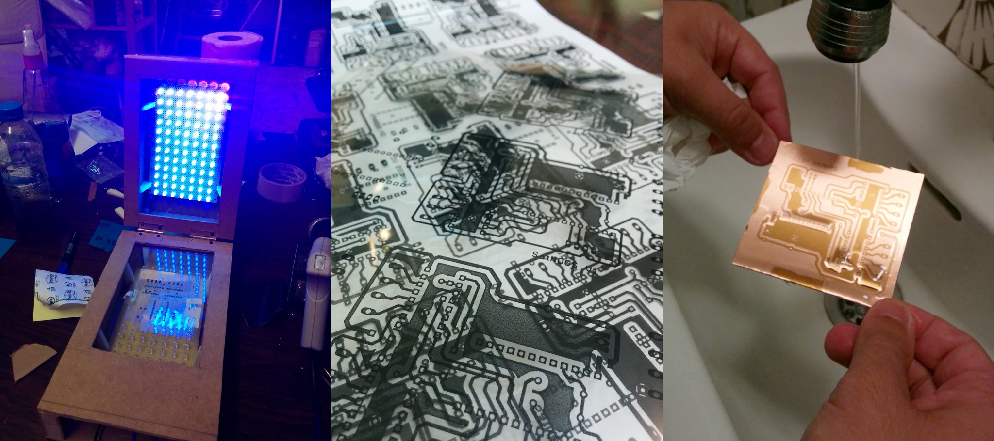
In a true hackerspace fashion instead of ordering the PCB we decided to built the capacity to produce our own (much needed moving forward). We could not settle for a simple single-side capability with no solder mask, so we shot for a typical side-project extravaganza :) What we ended up with was a double side capable UV exposer controlled for timing and after many tests the expertise to apply solder mask for uber cool finishing for our diy PCBs.
![]()
Back to SatNOGS specific PCBs the design was slightly changed from v1. We changed the capacitor, rerouted for optimal setup the board and thanks to [n0p] comments we added breakouts for unused Arduino pins (you never know what you will need!).
![]()
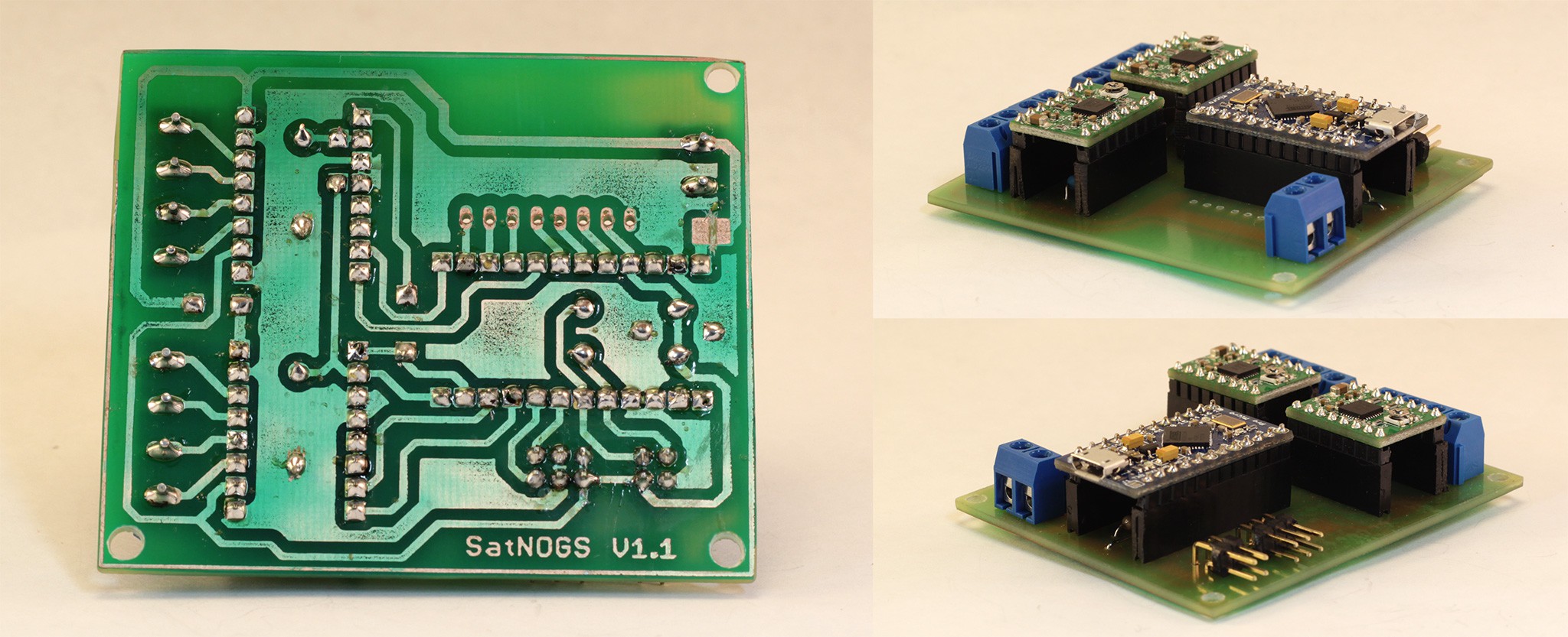
Production went smoothly and the PCB test showed that everything was in place correctly!
![]()
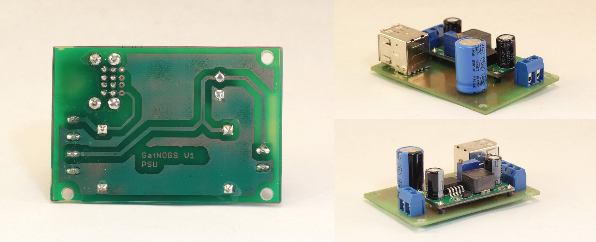
Having the finished v1.1 motor control PCB ready we thought that we could tidy up our power circuits too. That called for a PSU PCB tailored to our needs. Agis, our team electronics expert, quickly designed a PSU PCB based around a Voltage Regulator capable of having an input of 12V DC and an output of again 12V DC plus 5V DC stable through USB Type A too.
![]()
Production once again was smooth and we ended up with our PSU PCB. Pics below are from a slightly modified version with a cap (both designs can be found in our repo).
![]()
Detailed designs and Gerber files can be found in our Github repo
Next steps for our electronics will be to focus on the auto-homing circuits (using the handy breakouts!). A separate log on that will follow!
-
SatNOGS Network application development
09/18/2014 at 14:35 • 1 commentAs outlined in project description and previous logs, a central part of our projects is what we call "SatNOGS Network". SatNOGS Network is a web application running on a server that takes care of discovery of ground stations, registering of users, scheduling and job-detailing of observation as well as data collection and analysis once an observation is done.
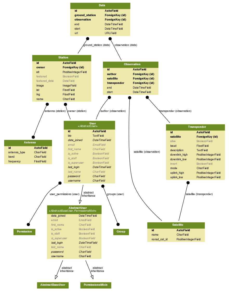
After 3 straight weeks of python/django hacking and almost 100 commits, we are proud to have a working prototype of the SatNOGS Network.
![]()
The model of the application is now polished and able to handle all basic operations for Stations, Users, Observations, Satellites, Transponders, Antennas and Data.
![]()
Next in line in terms of functionality implementation is the ability to plan observations based on user provided info (satellite, transponder etc) using SGP4 in python, and also a detailed view of Observation (with data and timeline).
The main page features a map with all ground stations, details about a featured ground station and latest completed and scheduled observations.
The code can be found (follow and contribute too!) here: https://github.com/satnogs/satnogs-network
A live development version of the website with demo data [WARNING ;)] can be found here: https://dev.satnogs.org/
-
LNA experimentation
08/20/2014 at 15:37 • 0 commentsSatNOGS is focused on TX operations for Low Earth Orbit (LEO) satellites. Most satellites in those orbits transmit signals in relatively low power (compared to GSO satellites). 100mW to 2W is a typical range for LEO. Given that power output and our RX assembly (yagi + dvb dongle for reception) a Low Noise Amplifier can really improve our RX capabilities.
We decided that LNA would be an integral part of our RX assembly early on, but we could not easily find something that would meet our requirements (bands, noise figure, cost, size etc). After browsing and researching a lot of different options out there, we stumbled upon LNA4ALL.
![]()
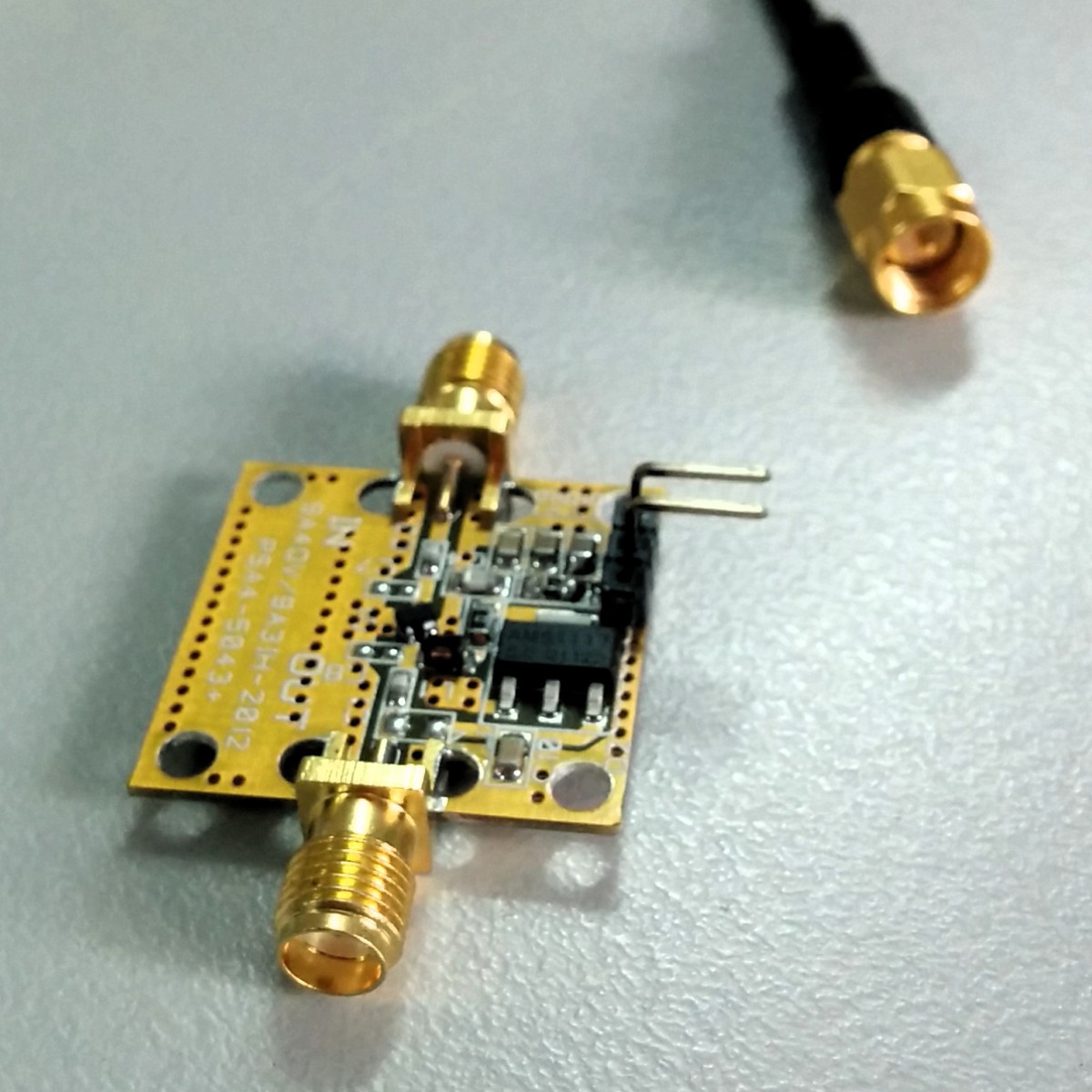
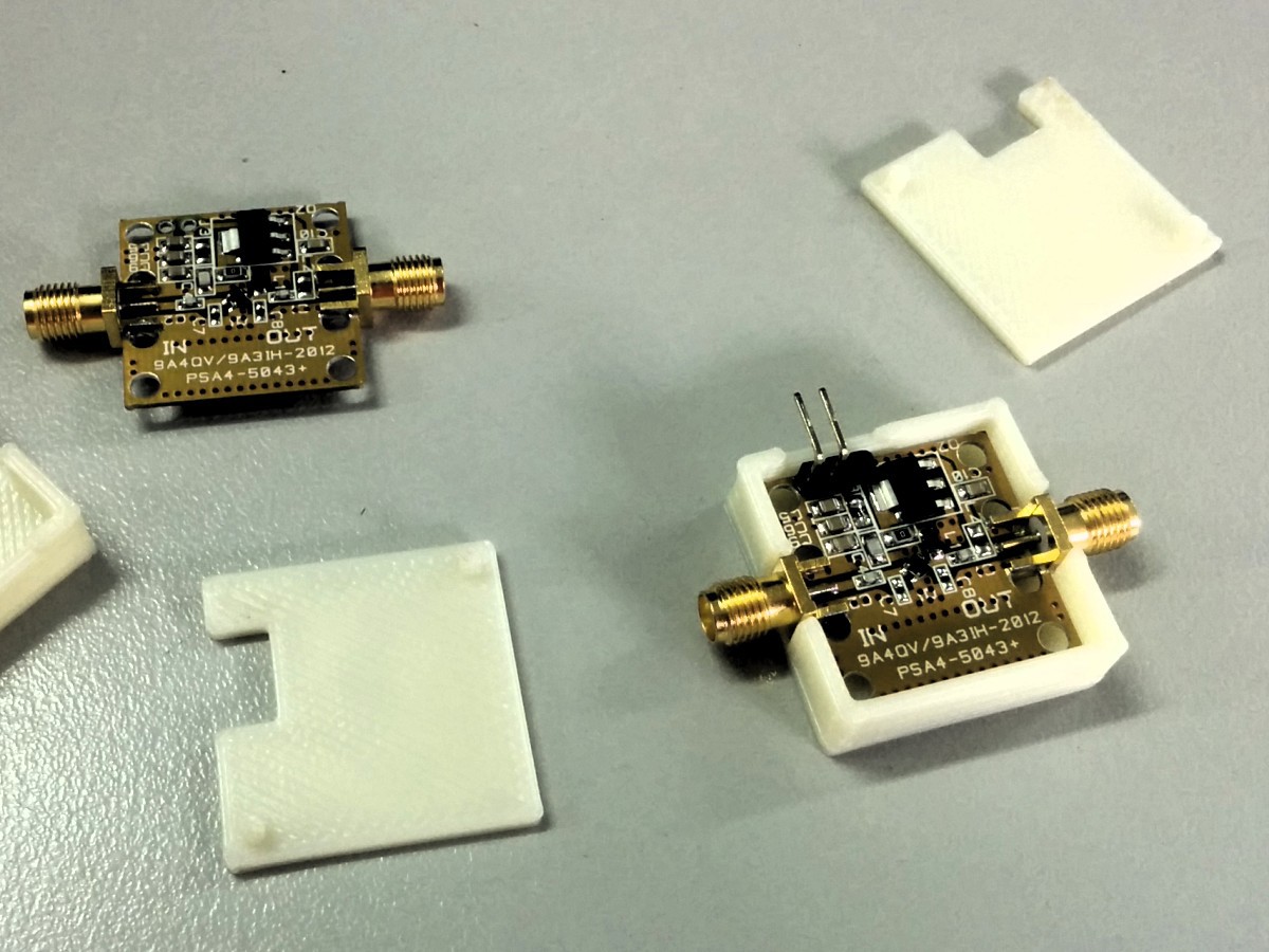
LNA4ALL [1] is a great project by 9A4QV. The amplifier is built around Mini-Circuits PSA4-5043+ E-PHEMT Ultra Low noise MMIC amplifier operating from 50 MHz to 4 GHz. Small SOT-343 package combine low noise and high IP3 performance with internal match to 50 ohms. With 20 Euros as a pricetag, this was the LNA we were looking for.
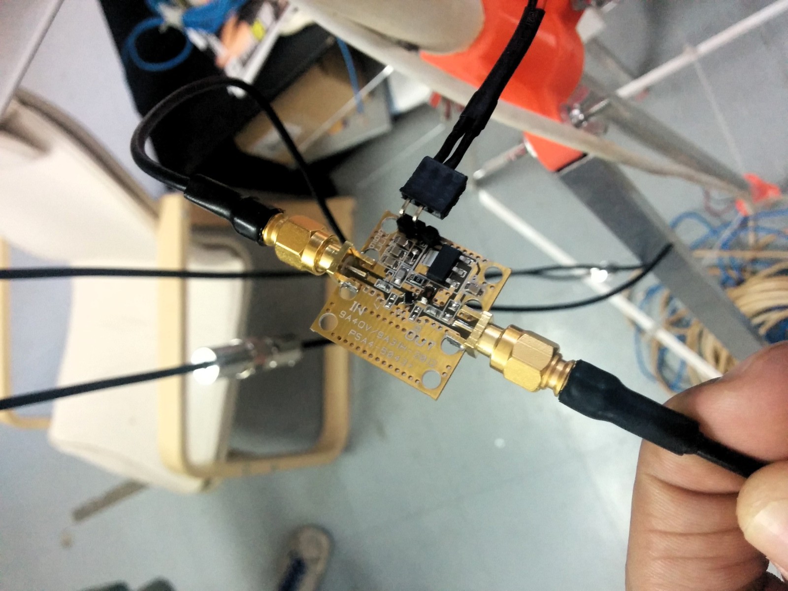
We are using our 5V output from the regulator we have inside SatNOGS as VCC for the LNA (required a tiny bit of modification) and the LNA is connected in line between our RX dongle and the antenna (using SMA connectors)
![]()
Initial tests are showing great improvement in our reception (tested against a variety of bands, encoding and satellites) making this LNA an irreplaceable part of our project.
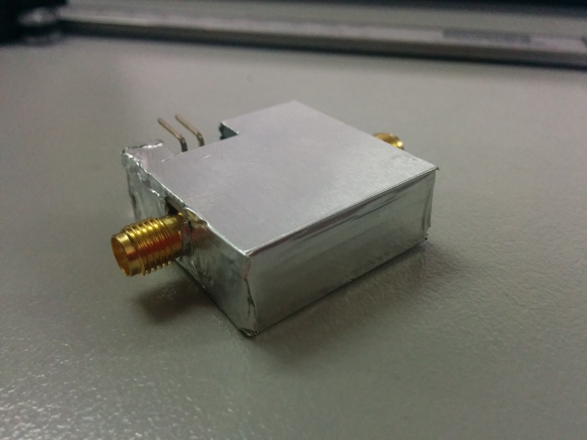
Proper shielding and housing should be in place, so we designed [2] and 3d printed quickly a housing for this LNA. Some grounded aluminum tape makes up for a shield.
![]()
More tests will follow, and we are designing new antennas and evaluating their matching.
![]()
[1] http://lna4all.blogspot.com/
[2] https://github.com/satnogs/satnogs-hardware/tree/master/Lna
-
Global Management Network - Intro and UX
08/18/2014 at 17:47 • 0 commentsSatNOGS as a project has been concieved as many Satellite Ground Station implementations (like the v0.1 which is ready) coupled together under a global Network that would enable anyone to utilize SatNOGS as a single platform for observations.
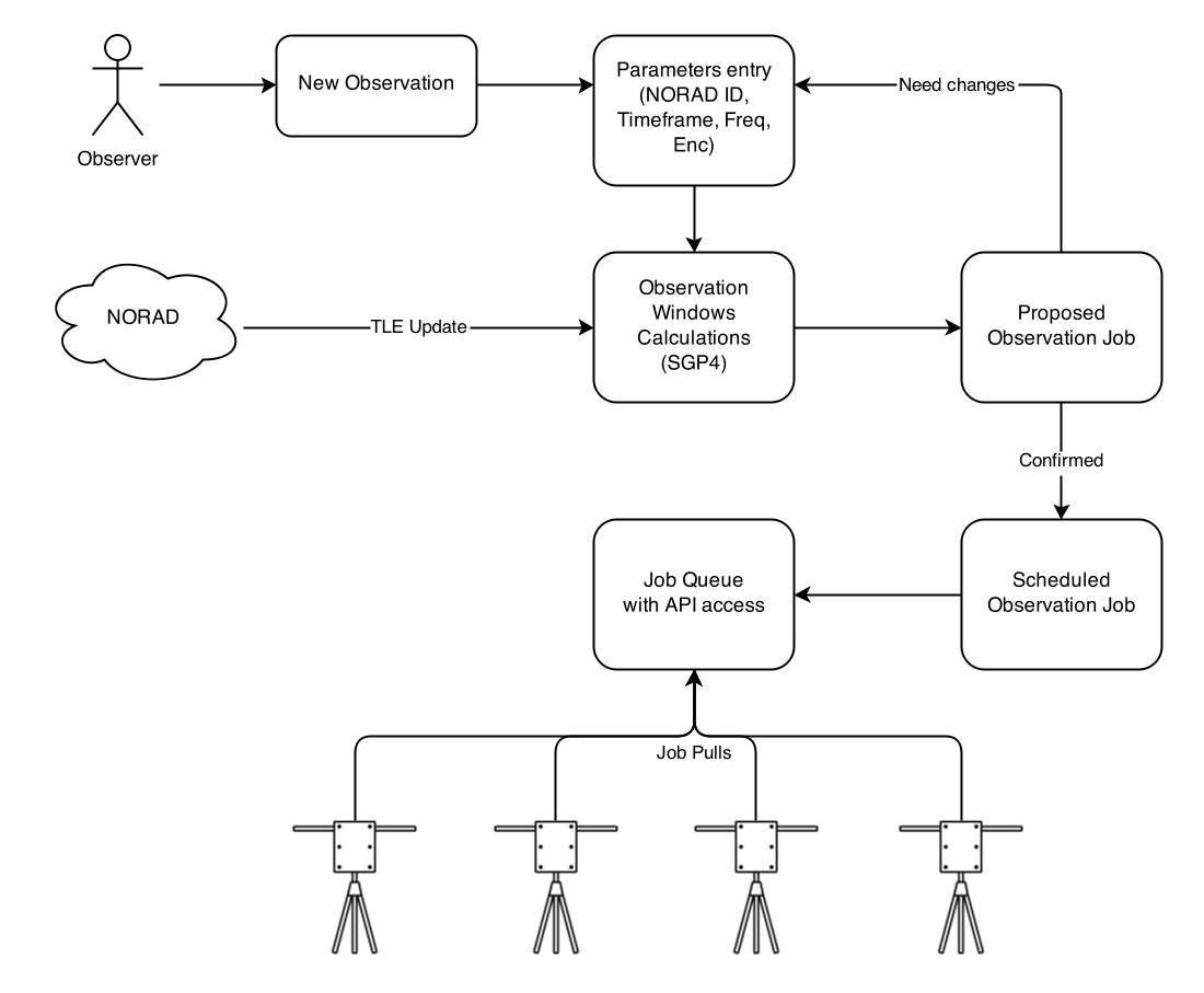
The UX idea is simple. An observer/astronomer/maker/hacker accesses our global Network via a web interface. Then she provides details about the observation that she would like to schedule like, which satellite, which band, what timeframe, which encoding etc. Then, having all the info , the system calculates the possible observation windows, on the available Ground Stations connected to the Network for the given timeframe (taking into account any tool, location and time constrains). Once the observer confirms the proposed "observation job" then it gets sent as a job to each Ground Station (GS) job queue to be executed when it has to.
![]()
GSs are gathering observations, decoding/recording them and sending them back to the Network, making them available to the observer (and the world!).
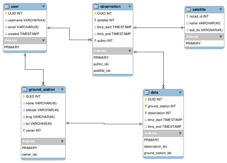
Here is a glimpse into the initial DB Schema of the Network (not all attributes are populated in the tables)
![]()
The general design of the Network part of SatNOGS constitutes a typical many-to-many scheduling problem (many observers to many ground stations) Interestingly enough projects have been developed for observations planning and scheduling on satellites like Hubble (HST) Projects like SPIKE [1] and ASPEN [2]. Those are examples of many-to-one scheduling system s and we have been looking around for implementations that would be similar to our proposed one. Unfortunately we haven't found anything closely related, thus we are building the Network part from scratch.
Given the expertise of our software people, we are building the application part on Django (python), and relying on rest APIs for communication with our ground stations. The first iteration of the network will be focused on a client-pull approach (versus a server-push) to eliminate any network restrictions.
Our challenges towards the global network are interesting. Given the data-heavy approach of the network (imagine all observations from all stations stored and indexed) we expect data storage to be a serious challenge. We are evaluating deep-storage as an approach to this, and we welcome any feedback or ideas around that.
-
New Electronics Shield
08/18/2014 at 12:56 • 0 commentsFor v0.2 of our ground station we have been working on consolidation of our electronics trying to minimize size and upgrade the components. Combined with the current minimized approach for the gear assemblies, this will enable us to deliver a smaller more rigid and reliable ground station.
The electronics that needed to be fitted in are the following:
* An Arduino. We selected Pico for the size advantage
* Two stepper drivers. We are using Pololu compatible A4983 based stepper drivers.
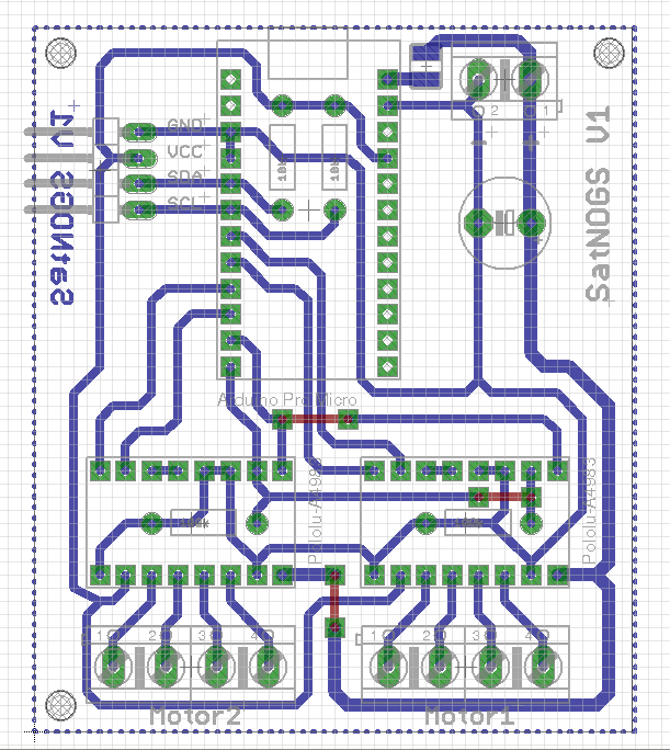
Agis (our electronics expert) designed an integrated board to fit everything in. Here is the result:
![]()
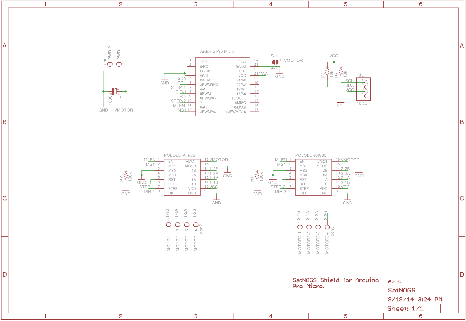
And the schematic:
![]() We are printing the PCB as we speak and will be posting a new log with the construction and testing.
We are printing the PCB as we speak and will be posting a new log with the construction and testing. -
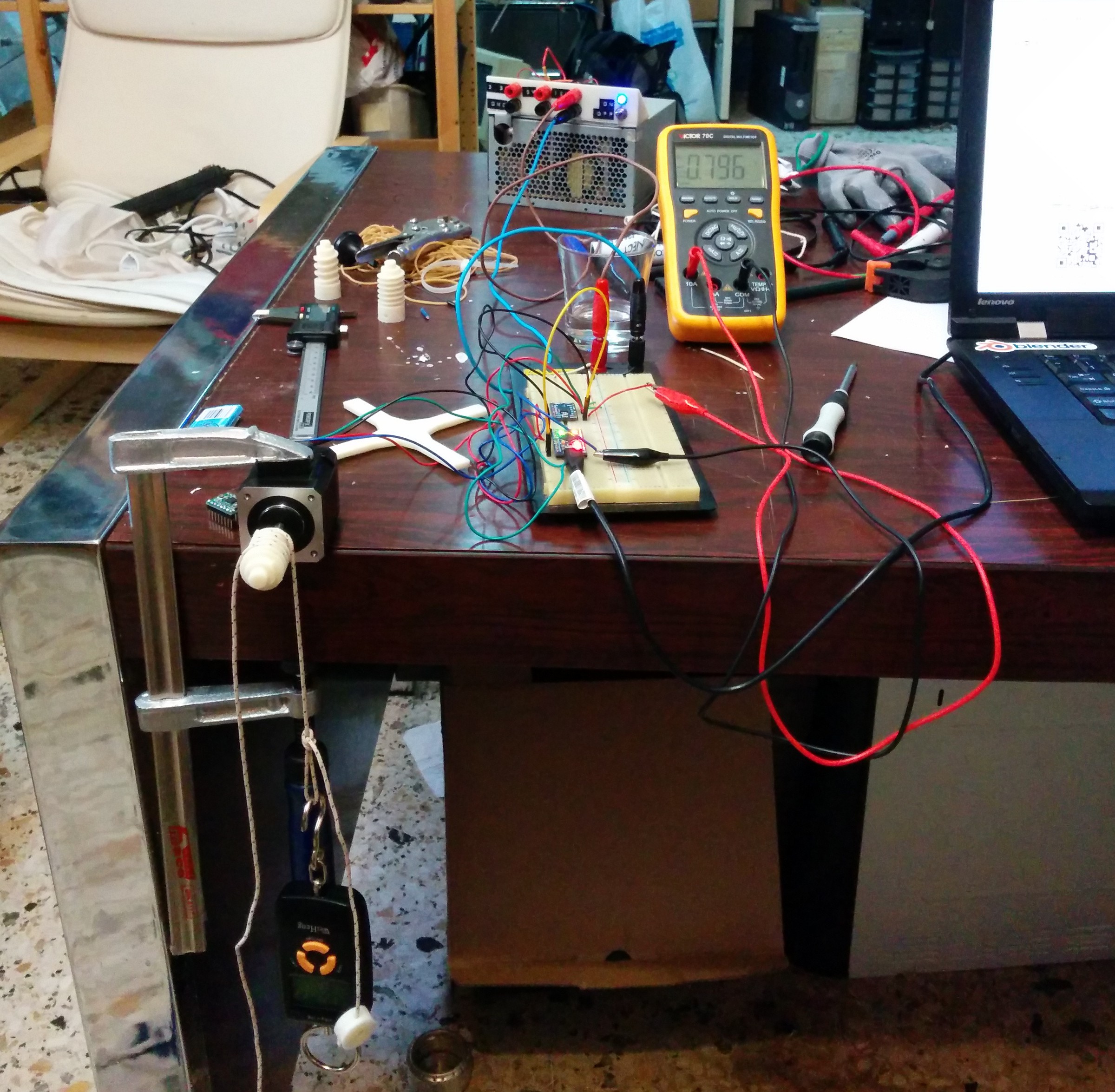
New design and NEMA17 motors
08/13/2014 at 13:36 • 0 commentsDespite the fact that NEMA 17 stepper motors were considered our best choice, at the time of our first design some old NEMA 14, spare parts from an old Rep-Rap, where available so we stuck with them. Last week, we received our new motors and did some tests. The first test was to find the optimal torque without overheating the (also new) drivers. Although we have some results, tests will be continued and we will come up with some numbers probably by next week.
![]()
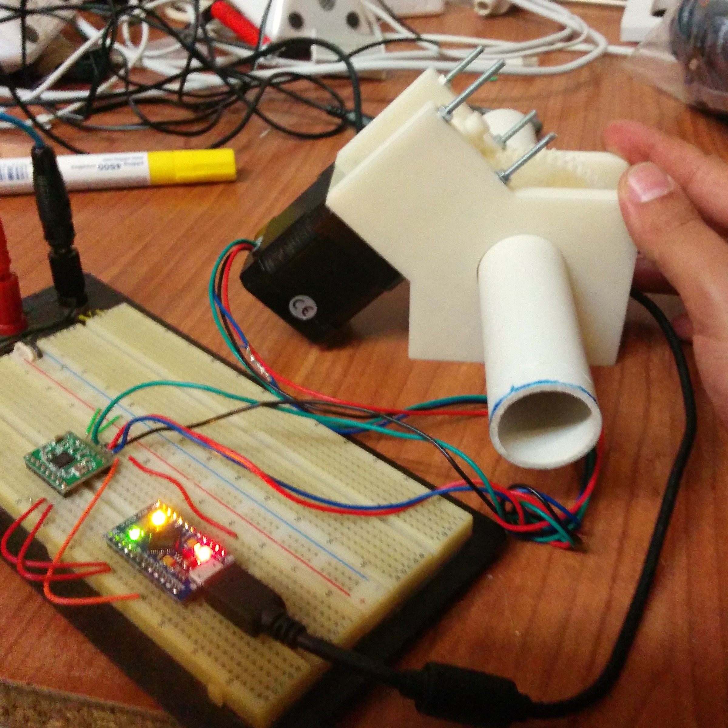
Additionally we are working on the new rotator design. We placed the motors on top. This way we managed to decrease the profile of the design a bit and also now the device is a lot more serviceable. Now you don't need to remove everything if you want to access the motors or the worm gear. We are also trying different designs in order to improve the connection between the stepper shaft and the worm gear.
![]()
SatNOGS - Global Network of Ground Stations
SatNOGS is an open source satellite ground station network, optimized for modularity, built using affordable tools and resources.


 We are printing the PCB as we speak and will be posting a new log with the construction and testing.