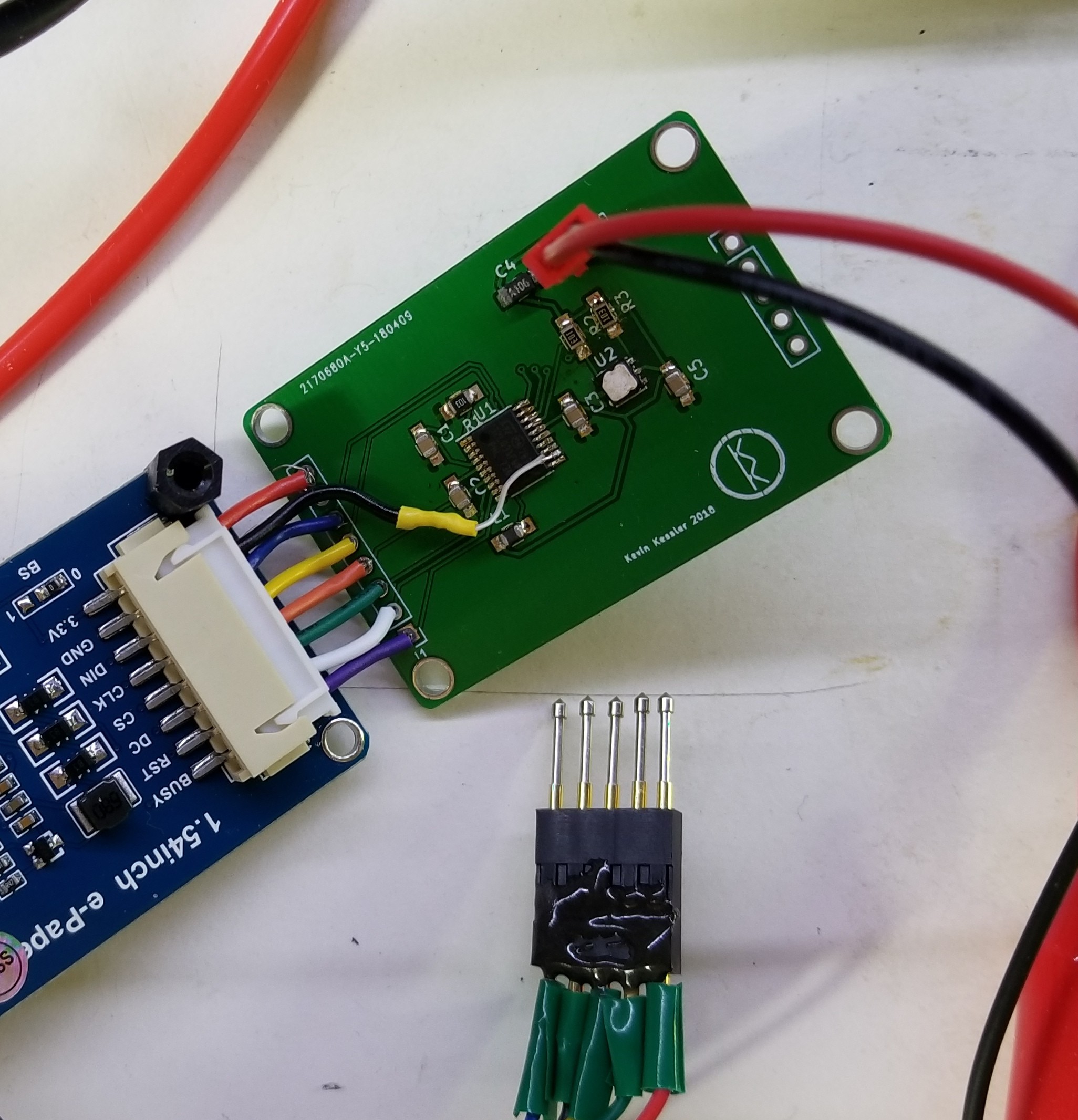
I've assembled my PCB complete with bodge wire for the switched GND:

I re-baselined the current usage, and found that rerouting the GND to switch off the device during standby has a price. During the update display phase, current usage is about 16% higher. I can't really figure out why, but there is no change if I set the GPIO switching the ground from Open Drain to Push Pull. Even with the higher current draw during the update phase of the device, the much lower standby current makes this an acceptable trade-off.
There is no difference between the current use from the breadboard to the PCB, which was a bit disappointing; I was hoping for some leakage or something from the capacitance in the bread board connections.
When you run the STM32l0 below 4Mhz, you can reduce the voltage on the core, from the default of 1.8 V to 1.2 V. This is done in the STM32CubeMX tool, under Configuration -> RCC. Voltage Regulator Voltage Scale 3 is the lowest value. That did not make a big difference in current consumption, though, with less than a 5% improvement in current at the lowest core voltage. It made no difference to the 2.25 uA standby current the device, which is not surprising since the core is shutdown in standby mode.
 Kevin Kessler
Discussions
Become a Hackaday.io Member
Create an account to leave a comment. Already have an account? Log In.