-
More ECL musings
12/21/2016 at 18:53 • 0 commentsI love logs !
I write stuff I think, and when it's over, it makes me think more...
The last log "Register set musings..." now looks somehow ridiculous to me. I blindly applied the approach I used for the relay version (#YGREC16 - YG's 16bits Relay Electric Computer) but the fanout tree becomes incredibly unsustainable. So I went back to the sketchpad and figured another latch topology.
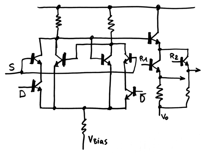
Still 6 transistors at the core, but organised differently, using a single-ended latch signal. This shrinks the driving logic significantly. Actually, the transistor count doesn't change, I have moved a "feature" closer to the latch cell, but I have also moved other things.
I start to play with transistors in series to create AND functions and applied this idea to the output buffer as well : a double wired-OR now replaces the two MUX8 for the read ports. All I have to do now is create three DeMUX8 to drive the respective enabling transistors, and each output of the DeMUX8s have a fixed fanout (16 for 16 bits).
![]()
Initially I had put the S (select) transistor at the low-side of the AND string but realised that the fanout would be always 2, since the base current would flow through both sides of the cell.
With the high-side version, the current flows either through the left or the right side because D and /D are mutually exclusive.
I am deliberately choosing asymmetric, non-ECL signals as a compromise between speed and parts count. I know I'll have a few issues with signal levels/swing because the bases will end up at different voltages, but I'm ready to increase the signal swing. I just want to keep the parts count as low as reasonably possible, without using xTL circuits...
20161225: More thinking
I now get "why" the "series" topology is often avoided, at least with bipolar transistors. The base current (the switching control signal) goes to the emitter, and with a hFE of 20, the margin is reduced. The bipolar version with higher gain will probably solve this, thanks to lower control current (better sensitivity) but I have yet to solve the current issues.
For the input ports, D and /D will inject some current (base to emitter) and slightly increase the common floating node's voltage. But since D = / (/D), there is always current (of roughly the same value) going through one of the branches. There shouldn't be much problems (except maybe during state changes) and the common node voltage should remain the same (more or less).
Things get ugly at the output. Base currents everywhere and necessary level shifting... Unless I shift the Vo node down to 0V ?
-
Register set musings...
12/12/2016 at 01:38 • 0 commentsThe critical part of the "bitslice" architecture defined by #AMBAP: A Modest Bitslice Architecture Proposal is the register set. It uses quite a lot of parts ! An 8-registers implementation with 16 bits each requires 128 bits of storage ! So that's a critical part to optimise, for all kinds of good reasons: parts count, power draw, cost, space and of course : speed...
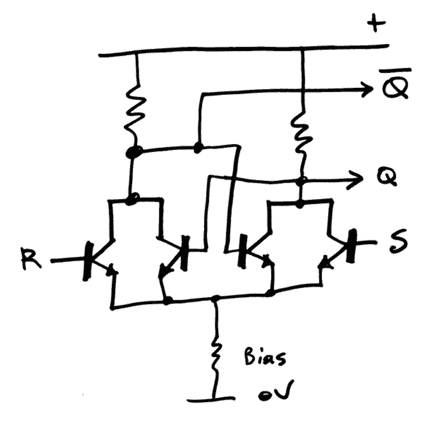
So what's the smallest bit-storage element ? The R/S flip-flop requires 2 storage elements and 2 "upset" or "override" transistors. A 128-bits set requires 512 transistors... yet it could be worse. And I don't even count the "interface"/buffer transistors (that's 640 now).
![]()
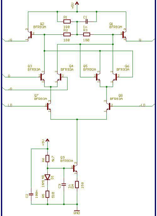
That's only 5 transistors instead of the more complex structures (such as the flip-flop implemented by Dieter)
![]()
But I can't really afford 9×128=1152 transistors. Well, I could but if I could avoid it...
Because the latch is only one element : we have the write select and the two read select circuits !
The write select needs one transistor to drive the set line and another to drive the reset line, that's 6 transistors (plus the output buffer). This is now somewhat equivalent to Dieter's circuit (with only one output buffer transistor).
However Dieter's circuit is fully differential and requires two differential inputs, or 4 wires, which also increases the number of driving transistors. The differential LD signal might be the hardest part because the D input is a simple value that can be "faned out". The clock signal however must be steered to the appropriate register (let's say one of the 8 registers). For the simpler R/S flipflop, I think I have found a simpler method: it's unipolar and uses less transistors (again, buffer transistors are omitted):
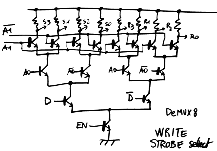
![]()
This is another conjunction between my relay musings and Dieter's experiments (who coined the relay/ECL equivalence for decoders)
The D and /D inputs could be coming from a previous flip-flop, or even merged with the buffer outputs (I should check this and the voltage levels might be incompatible but hey... maybe complementary transistors could help here ?)
The cool thing is the EN input : the A0-A1 inputs can take some time to settle (and ripple down the fanout amplifier circuits) and a single EN strobe will then propagate to only one output. The EN signal can come from the same signal that drives /LD of Dieter's latch.
I'm OK to sacrifice a bit of speed in order to save transistors and I'm not sure this circuit runs as fast as a NOR3-only D-ECL circuit but I got fast transistors so what. Furthermore, this circuit seems to work as well for Silicon transistors :-) (it's only a matter of setting the correct bias currents and voltages)
Parts count for the writer tree : 2 or 3 transistors per latch, depending on the necessity of a buffer. Maybe mixed PNP and NPN could be used to save more parts.
The tree could be "cut" to reduce its height (in case it causes problems). Since 8×2=16 outputs are required, a 2-level system (with two 2->4 decoders) could be used... I'll see later.
The read MUX tree reuses the same "unipolar" ideas, though NOR3s and NOR4s can also work nicely.
![]()
Now, you can't deny that this circuit is pretty compact: it uses less transistors than NORx circuits and I'm ready to accept that it's not as fast as plain D-ECL.
Cost for a tree: 3 transistors per latch. Total per bit : 3 for write, 5 for latch, 6 for read. That's 16 transistors per bit, or 2048 transistors (at least) for a 8×16 register set... and I didn't count the input/driver latch. This amounts to most of my stock of AF240...
-
The "language" of ECL
11/13/2016 at 15:30 • 4 commentsAs I start to "get" ECL, I discover its topological language and various methods to do the same thing.
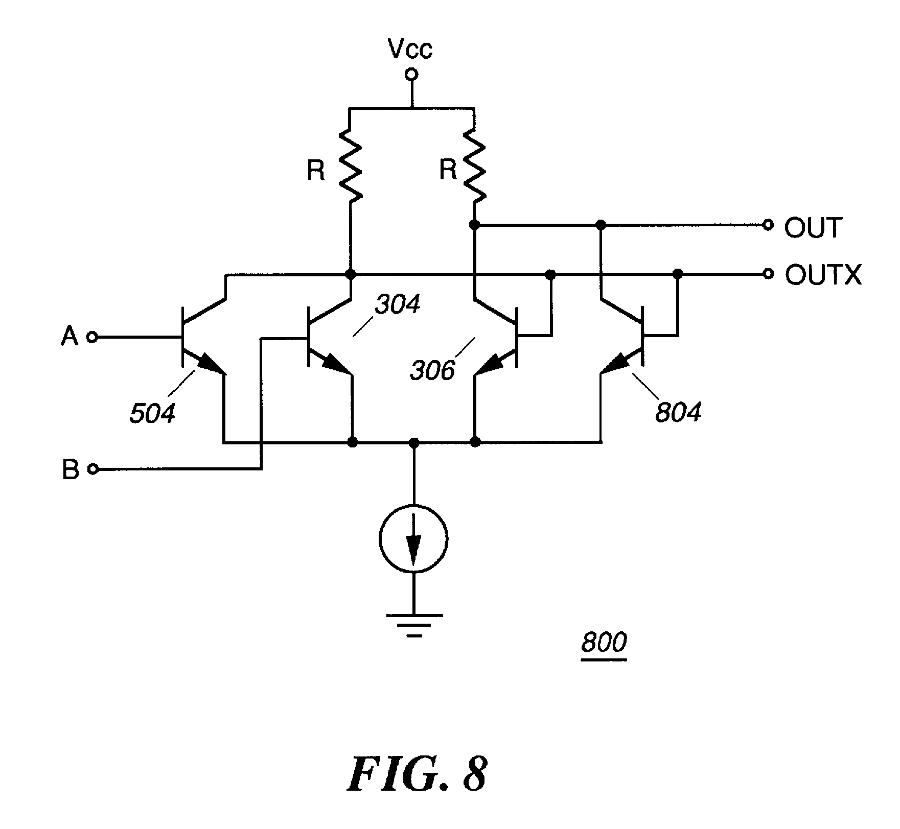
For example a OR gate, without the common bias node of MECL10K, found in an old patent http://www.google.ch/patents/US5831454 :
![]()
So that's one thing to do : compare this topology with the common-zener one. As germanium is pretty sensitive, I wonder which circuit will work best.
The latches are another concern, apparently there are a few ways to make them, and 6 transistors per latch seems to be the minimum (12 per DFF, similar to other technologies).
Update 20200524:
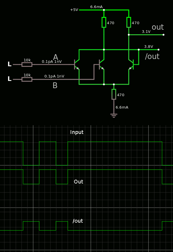
Thank you Falstad :-)
The 2 transistors on the right are just to balance the current because of the gain... So I try with only one.
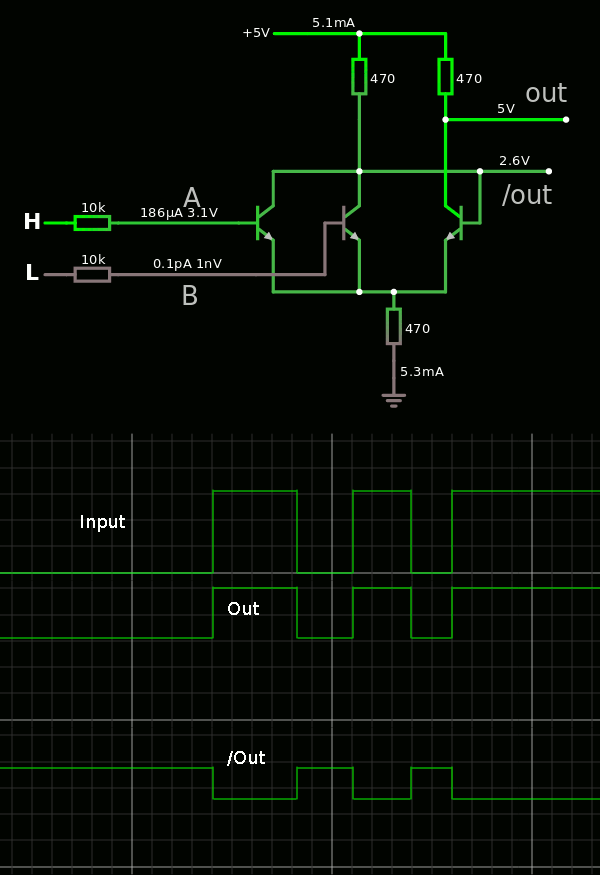
The sims show that the output levels are not comparable :
![]()
![]()
The inverting output has a lower range than the non-inverting output... It is indeed clamped by the base of the right-hand transistor.
Finding the right values for the resistors is another challenge, it's not mentioned in the patent (?)
With all resistors at 470, I find :
Vin-h : 3.1V
Vout : 5V - 3.1V
V/out : 3.8 - 2.6V
Anyway this is an unbalanced system because in "normal" ECL the branches are mostly independent.
The non-inverting output needs to be level-shifted...
And it is a system that has about 1.2V of hysteresis !
-
Fastest Germanium ?
11/07/2016 at 21:08 • 3 commentsHow fast can germanium transistors compute ?
This question might receive an answer soon.
While visiting one of the few remaining electronics parts stores of Paris, I found that they have a little stock of Ge. And I got their last AF280. From the datasheets:
This transistor is particularly intended for use in mixer and oscillator circuits up to 900 MHz in diode tuned tuners.
So the intuition worked (higher number means better performance, right ?), this transistor is faster than the 500MHz AF240 (though only by 10% because its transition frequency is actually rated for 550MHz) and the datasheet claims a power gain of 16dB @800MHz (power gain of approx 40, or amplitudes 12 ?) to a 2K ohms load (compatible with an ECL gate impedance). Too bad my DDS can't go so fast, but I'll try to hack a picosecond pulse generator...
I got 13 AF280 and if I don't make mistakes, I might be able to build two NOR2 or NOR3 gates. Enough to test some logic and/or a flilp-flop :-)
It just appears now that the answer I might get is not of the kind I expected intially.
With such fast transistors, my lab tools are already too slow. I consider building a picosecond pulse generator but that won't help much.
Furthermore, if I build a globule that is clocked so fast, I have another problem : memories. Latency and bandwidth will be hard to match with the expected means and I'll have to resort to using fast silicon chips.
20170106: I found a batch of AF439, roughly equivalent to the AF280/279, so I might be able to build more than a couple of gates :-)
It's going to be fun, though, since the hFE is ">10" (http://alltransistors.com/transistor.php?transistor=21851). The frequency is rated at 400 and 800MHz depending on the sources, but this speed will be held back by poor amplification.
-
Inventory #2
10/31/2016 at 15:18 • 0 comments(updated 20161230)
(updated 20170106)
(updated 20170326)
supersedes log 1. Inventory?So I got the 4-channels 200MHz DDS, the 4×300MHz scope, as well as a 2×200MHz DSO, and a new supply of AF240S.
Ref hFE Ft
(MHz)I
(mA)U
(V)P
(mW)Fab Qty G106T 60 35 25 60 Telefunken 300 AF137 60 35 25 60 Telefunken 300 AF138 60...100 40 25 60 Telefunken 1000 AF178 >20 180 10 25 75 Philips 100 AF200 >30 200 10 25 225
(??)Siemens 600 AF240 25 500 10 15 60 Siemens 10000 AF439 >10 400 10 15 Philips 540? I can now choose between 3 classes of Ge transistors :
- 1600 medium-gain but slow PNP G106T, AF137, AF138 (hFE >60, Ft < 50MHz)
- 700 faster but lower gain PNP AF178, AF200 (hFE>20, Ft > 100MHz).
- 10000 very fast, low voltage, low gain PNP AF240S
The slow transistors can be used for I/O ports. For example keyboard input, LED drivers, GPIO, serial I/O... Probably using saturated logic as well, whereas the AF240 will use ECL.
I wonder if I can make 25MHz synchronous counters. That would enable me to work with a VGA display, reusing some tricks implemented by @Ted Yapo for #PIC Graphics Demo.
No idea about how to implement some memory, though. I don't want to suffer the magnetic/core memory hell... I will certainly cheat and use modern CMOS ASRAM :-)
-
If in doubt, try to investigate how Seymour Cray would have solved the problem.
09/21/2016 at 23:20 • 0 comments@matseng just sent me this link:
http://6502.org/users/dieter/decl/decl1.htm
This is just awesome :-)
25) Transistorised ECL/DECL logic is a nice playground
    for wasting time, money and components in a creative way.
I feel vindicated !
-
Starting to "get" ECL
09/20/2016 at 23:08 • 2 commentsHaving a Cray-1 type board and some documentation about it, it only came recently to my knowedge that it is mostly made of (N)OR3 ECL gates. What I didn't realise is that it's not comparable to, say, a 74F00.
First, larger logic fanout : 3 inputs, instead of 2. (edit : better ! OR/NOR4 and OR/NOR5 ! please disregard the mistake in the rest of the text) It changes everything. Two dual NOR3 in ECL can do the same as 4 NAND2 in TTL, in the same package size. You can easily make a latch with bells and whistles, and less critical datapath than, say, what #NEDONAND homebrew computer can do...
Second, you got complementary outputs. You can use the inverting or non-inverting output, or both. With NAND2 (74F00) you must waste another gate to invert it, and even risk adding jitter/glitches...
This is another killer characteristic. OK ECL consumes more, and uses more transistors but it's not only faster, but uses less gates overall. So it now makes sense to me that Seymour Cray chose this, and trying to design a circuit with it shows that it's actually very sound.
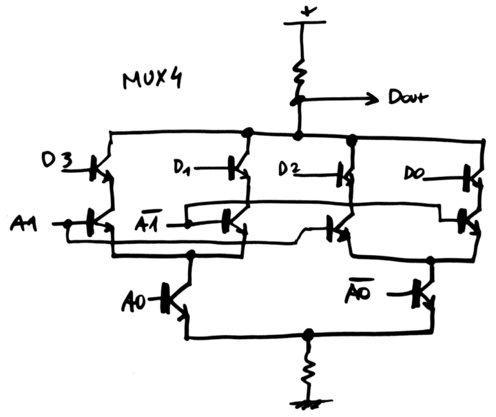
I have been wondering today how to design a 2^N multiplexer. This is simply a circuit that selects from one input out of 2^N. Nothing fancy but since there are alternate ways to design an ECL latch, I wondered if there was an ECL MUX2 topology. ECL does not allow a signal path to cross the gate directly so it must be "computed" by transistors. X = (A & S) | (B & /S)
The transistor topology does not look good because the AND parts require two transistors in series. This is electrically more complex than the canonical NOR gate.
Now what happens in NOR3 world ? A MUX4 would be originally written as
X = (A & S1 & S2) | (B & /S1 & S2) | (C & S1 & /S2) | (D & /S1 & /S2)
OK let's say that we have a (N)OR4 for the main output. The 4 inputs are fed by ANDs. But wait,
X = A & B = /( /A | /B)
So the ANDs can be transformed into ORs with more bubbles. And now comes the bubbles-pushing games !
The ANDs will use the complementary output of the NOR3 gates, so this comes "for free". The AND's input bubble will come from the latch's complementary output. And S1 and S2 will use both complementary outputs. The MUX uses no inverter anywhere, and only 2 levels of logic gates !
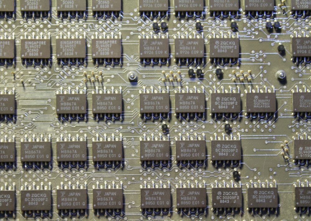
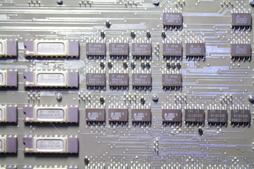
Close view of a Cray-1 IO board. Fairchild and Motorola ECL chips, the tiny black dots are 2-resistors divider networks for termination. CRI chips too...
What's the pinout of the 16-pins small gates ? I can't make sense of it, 3 inputs + 2 outputs = 5 pins, add 2 for GND and Vcc. 2 NOR gates => 12 pins, 3 NOR gates => 17 pins. This does not match. Help.
Drive strength is another convincing factor (for Seymour Cray at least). For long distance communication, just use the pair of complementary outputs and send them over a twisted pair. Add some termination at the receiving end and use the signal(s) you need.
ECL gates are pretty sensitive and have low swing (the lower, the faster, and Germanium has a low threshold voltage). This helps with fanout, if the buffer transistor's gain is high enough. I wonder how many gates can be driven by my germanium transistors, the AF240 has a quite low hFE...
Fanout is to be determined.
Looking at Dieters's MT15, I think about @roelh's ALU with this picture:
![]()
My brain did not "see" the propagate/generate units but the couple of MUX4 of the ALU. But I realise now that MUX4 trick might be the best idea so far, and it would save a XOR layer for one operand... And I've found that MUX4 totally ECL-friendly :-)
The big problem now is to deal with all the fanout and control signals. Dieter had a LOT of troubles with that... -
Inventory
09/20/2016 at 02:44 • 0 commentsThings are getting out of hand !
- I recently started #AMBAP: A Modest Bitslice Architecture Proposal : this is a sort of framework where I can examine and compare different technologies, with the goal of performing one function (ALU+registers). This gives us a list of gates to design : AND, OR, XOR, MUX, latch, buffer...
One bitslice can be implemented with different types/references of transistors and their performance is compared easily. - I'll get new tools soon : a 200MHz DDS and a 4×300MHz scope. Just in case ;-)
- I made a little inventory of the available (hoarded ?) germanium transistors: (the silicon ones are there ) Superseded by log 4. Inventory #2 ?
Ref hFE Ft
(MHz)I
(mA)U
(V)P
(mW)Fab Qty KF167 NPN ? 250 ? Tesla ?
siicon ?300? G106T PNP 60 35 25 60 Telefunken 300 AF137 PNP 60 35 25 60 Telefunken 300 AF138 PNP 60...100 40 25 60 Telefunken 1000 AF178 PNP >20 180 10 25 75 Philips 100 AF200 PNP >30 200 10 25 225
(??)Siemens 600 AF240 PNP 25 500 10 15 60 Siemens 10000 The G106T and AF137 are pretty much the same (same manufacturer, same characteristics...) and just a tiny bit slower than the AF138.
AF200 is quite faster but the power rating I have found feels inaccurate. The package is a classic-looking metal can, much smaller than the TO-5 of the AF178 rated at 75mW. In comparison, the slower AF13x are in the funny-looking "long can" TO-18 package.
Anyway, I have two sorts of transistors :
- 1600 medium-gain but slow PNP (hFE >60, Ft < 50MHz)
- 760 fast but lower gain PNP (hFE>20, Ft > 100MHz).
In the context of a bitslice, the fast transistors would be used for the adder's carry chain, while the slower would do the rest. Since they have a higher gain, they could be tuned to consume less current and save some energy (which will translate into less drift during operation ?)
Anyway, I can already imagine implementing one bitslice with each one of these references and see how the Ft (transition frequency) translates into raw operating speed.
...
Oh wait, today it seems I can get a ridiculous amount of AF240...
2020 : Jaromir sent me his stock of eastern germanium and this is getting crazy :-D
However the inventory is not easy... - I recently started #AMBAP: A Modest Bitslice Architecture Proposal : this is a sort of framework where I can examine and compare different technologies, with the goal of performing one function (ALU+registers). This gives us a list of gates to design : AND, OR, XOR, MUX, latch, buffer...
Germanium ECL
How fast can germanium transistors compute ? And how much current will that draw ?
 Yann Guidon / YGDES