 Ivan
IvanOur team was experiencing some difficulties when installing and removing the electronics assembly from the 3-d printed housing. The trouble lies in the where you have to apply force to insert and remove the electronics, it is on our joystick board which is attached to the rest of the electronics with only a row of mated male and female headers.
The joystick board is connected to the main interface board by sliding the joystick board right angle female headers onto the straight male headers from above. The electronics are inserted into the housing longitudinally so a pushing force is typically applied to the face of the joystick board to securely insert the electronics. Conversely, if the electronics have to be removed a pulling force is applied to the joystick board to remove the entire electronics assembly.
So to alleviate this problem and allow for a smoother install or removal procedure I rearranged the headers on the main interface board and joystick board to mate parallel to the length of the main interface board and housing. Now the bulk of the electronics assembly can be inserted into the housing with an area on the PCB that can sustain a pulling or pushing force. Once everything is secured you can install the joystick board by sliding the male headers into the right angle female headers from the front.
It may be hard to see it in my board layout but here it is...
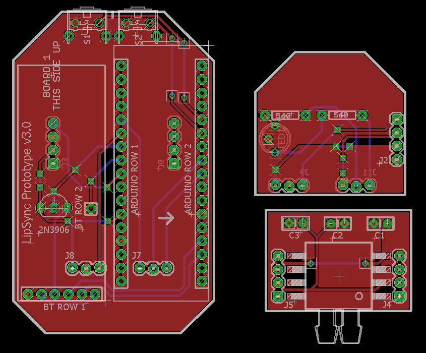
Upon some final inspections and measurements, this will probably be the board layout I use for our next batch of PCBs.
Until next time!
-Ivan
Discussions
Become a Hackaday.io Member
Create an account to leave a comment. Already have an account? Log In.
Any useful comments are appreciated, this only my second time designing a PCB.
Are you sure? yes | no
Are the switch frames connected to ground? It looks like they might be isolated. Electrically connecting them might buy you just a little more ESD resistance. I always connect them out of habit.
It doesn't matter electrically with this circuit, but you could also widen the tracks especially ones connected to through-hole headers. The headers (and switches) are likely to take some mechanical abuse, so I always use the largest pads feasible and wide tracks to them to provide a little more resistance against the tracks breaking as the pins are flexed. I'm not sure it helps, but since you have plenty of room, it won't hurt. In some cases, I also route redundant tracks on both top and bottom layers for the same reason (although not when I need a solid ground plane). Since most of your signals are low speed, you could probably afford to do this in places here.
I don't do this professionally, so take my advice with a grain of salt :-)
Are you sure? yes | no
Hey @Ted Yapo thanks for the feedback. I just checked the switch case and you are correct they are not connected to ground, I will make that mod right now.
Using long pads for the more heavily abused headers would be great idea - thank you.
As for the redundant traces, I broke out my Electromagnetism course work to see if a branched trace onto itself would create an "antenna" of sorts - we are trying to reduce electromagnetic interference as best we can, since these could be used around sensitive medical devices etc. Parallel-ish current paths shouldn't create any additional magnetic field, if anything it would drop the B-field between the two traces.
I will take the wider and redundant traces into consideration, I want to think about it a bit more. However the grounded push button casing and long pads - 100%.
Thanks boss!
Are you sure? yes | no