Wow it's been 2 weeks since my last update, that's because I've not had much to report - even though I've been working my tail off on this... seriously - like 5 or 6 hours of sleep a night, that catches up with me after awhile :(
So - here's the deal; I got the AD724 all hooked up and I was super excited to test my code and the HSYNC timings - I plugged it all in and..... basically just a flickering monitor with nothing really to show.
So I poured over my ASM code for a long time, found lots of small timing bugs (this NTSC timing has to be pretty perfect) and tested... didn't work so I repeated the progress over and over again.
Speaking of NTSC timings - OMG there are sooooo many different references and they all very slightly! For example; if you're trying to figure out timings for sync pulses, visible scan lines, front porch, back porch, etc. most of the documents vary slightly - here are some examples of ones which are different:
https://bradsprojects.com/generating-video-signals-with-a-microcontroller/
https://people.ece.cornell.edu/land/courses/ece4760/FinalProjects/s2006/kwj5_mhw23/index.html
http://www.sxlist.com/techref/io/video/ntsc.htm
https://www.maximintegrated.com/en/app-notes/index.mvp/id/734
... I could go on...
But this lead me to the conclusion that televisions (and monitors) can be a bit forgiving (but not too much)... so why was mine showing nothing???
I decided to try ditching the color chip (AD724) and directly sending voltage signals (gray scale) to the monitor... after a few quirks in my timing I was able to get it to look good on two displays... my Goodwill monitor and my USB->Composite capture software... here are the bars:
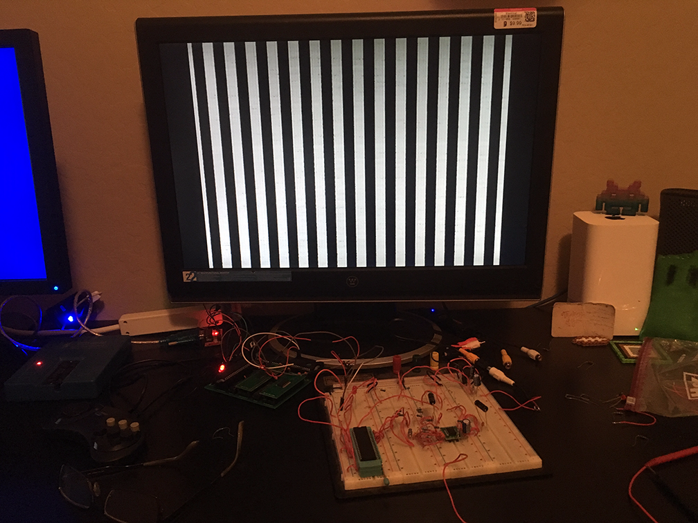
Hooray!!! That was an exciting moment - taken at 2:30am when I had to be up for work at 8:00am... totally worth it though :)
So now that I had the sync working on two monitors I decided to revisit the color chip... absolutely nothing was coming out of it - so I started pouring over the datasheet again.
http://www.analog.com/media/en/technical-documentation/data-sheets/AD724.pdf
To my horror I realized a minor issue.. the color input pins (RIN, GIN, BIN) maximum input values are 714mV. I never realized this - I had been blasting them with TTL 5V levels! I consulted my HW mentor and asked if I could have blown the chip... his response: "Totally". So! That's ok - I've got everything wired up to send the correct voltage levels and I just digikey'd off for a new AD724. As soon as it gets here I'll plug it in and see what happens! It should be here next week, so hopefully I'll update this within a week.
Thanks for reading! This is the most challenging and most rewarding project I've ever attempted :)
Discussions
Become a Hackaday.io Member
Create an account to leave a comment. Already have an account? Log In.