Quick status update - to help reduce the interference I needed to move the delay lines and the color generator chip (AD724) to their own board.
I attempted to do this and solder them all in, but it quickly became a mess of wires... partly because it's a bit complicated, but mostly because I'm a novice at this stuff.
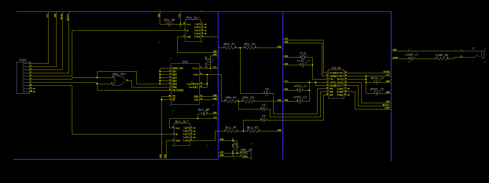
So - I decided to get a PCB made, this will contain the delay lines, color generator chip, and all of the resistors and capacitors needed. Essentially it will take the following inputs: Vcc, Gnd, HSync, red, green high, green low, and blue. It will then output a composite signal via an RCA jack.
This way the color composite signal will just be "done" and I won't have to worry about messing it up or making extra breadboard room when I move on to the next phase, which is wiring up a circuit to do the per pixel tile rendering... more on that later.
I uploaded the gerber files and the schematic to github, but here's a quick pic if you're interested:
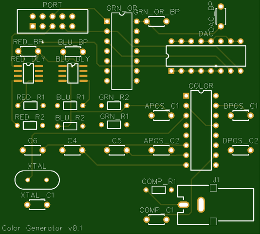
And here's a pic of what the PCB should be like
So...we'll see...hopefully this works as expected. This phase has been slow going but good, I've learned a lot about chip/signal delays and interference.
I'm excited to move on to the per pixel rendering!
Discussions
Become a Hackaday.io Member
Create an account to leave a comment. Already have an account? Log In.