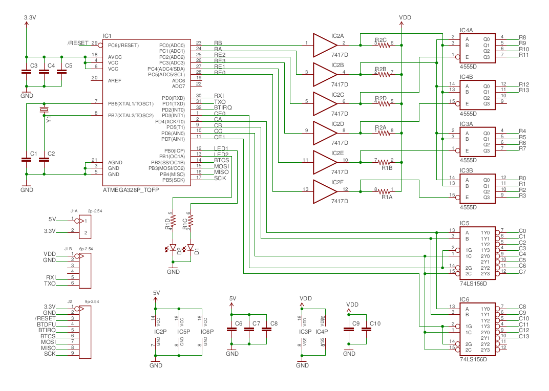
To recap, the lollipop interface circuit will consist of:
- ATMega328P microcontroller
- MC14555P CMOS high-side row multiplexer
- 74LS156D open-collector column multiplexer
The CMOS part will have a variable supply voltage. To allow it to remain compatible with the control signals from the microcontroller, I'll use a buffer IC to perform level conversion. By using a part with open-collector drivers, the outputs can be pulled up to the CMOS voltage:
- 74LS07 hex non-inverting buffer with open collector outputs
With the addition of pullup resistors, a few decoupling capacitors and a crystal for the microcontroller to allow accurate timing, it should be possible to design a relatively small board, given the low number of components.
I would also like the option of a bluetooth interface, to allow pairing with a smartphone. The SPI version of the Adafruit BLE module looks suitable, so I'll try to support this. This is a 3V module, so it makes sense to run the microcontroller at 3V as well - this won't cause any problems with the control signals for the 5V 74LS parts, as a quick look at the datasheets show that the levels remain compatible.
Although I have some experience of building on stripboard/veroboard, I've never designed my own PCB before. So it will be a challenge to make a well laid-out board while learning how to use the software tools.
After doing a bit of research, I decided to try Eagle, mainly due to its ubiquity and the availability of a Linux version. I can use the freeware licence with this project, as it's non-commercial and the board size will be below the imposed limits.
Here's the completed circuit diagram, as drawn in Eagle:
Discussions
Become a Hackaday.io Member
Create an account to leave a comment. Already have an account? Log In.