 WΛLLTΞCH
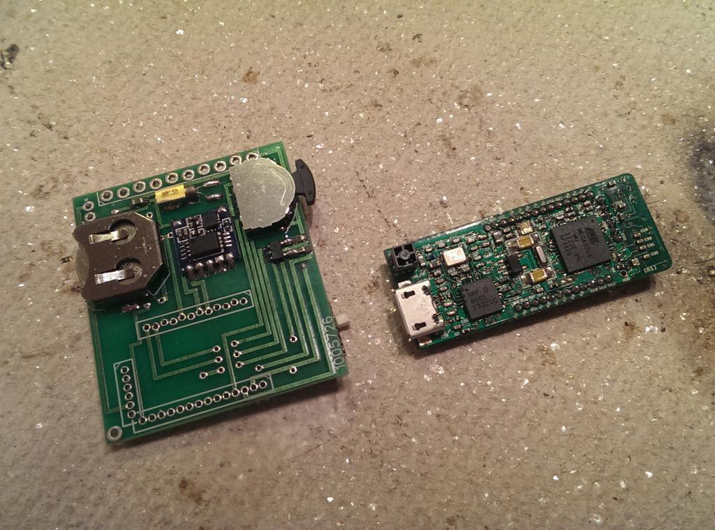
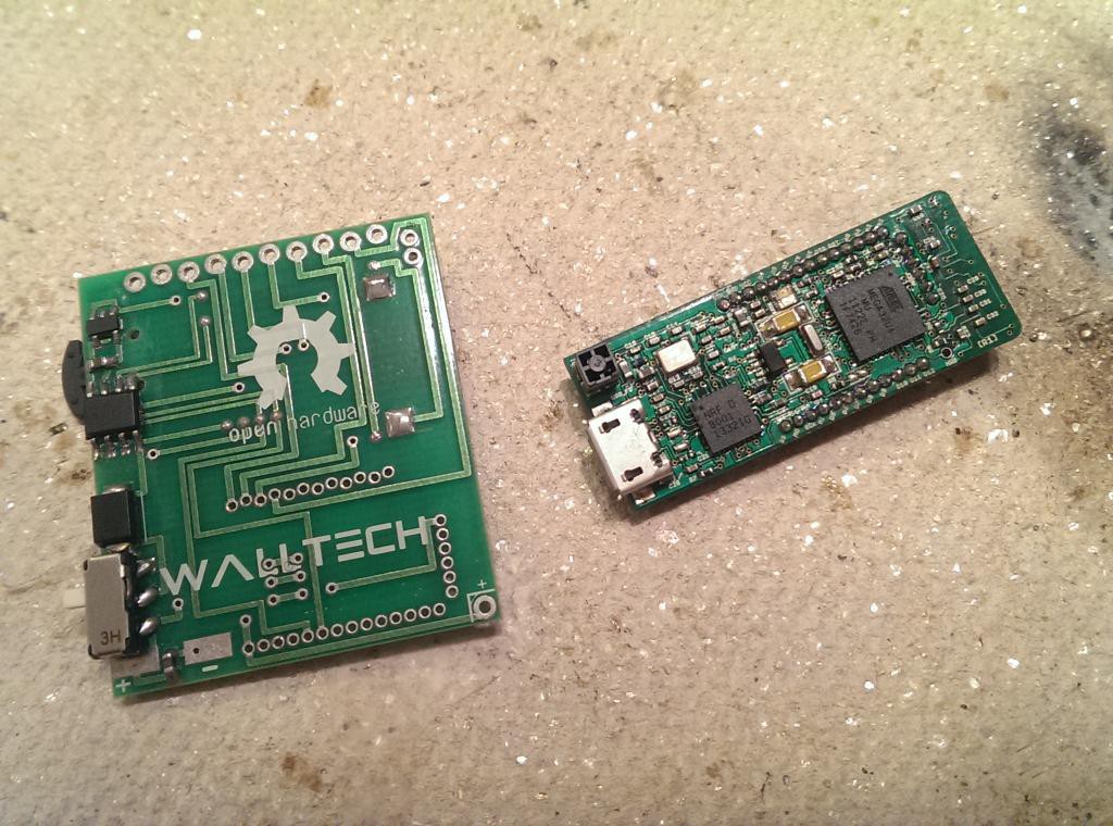
Labor day weekend I had some time to populate the pcb for the smart watch and do some preliminary testing, but left off the expensive IMUduinoBTLE and OLED display until I was fully confident in the design. After all the ICs and passives were soldered on by hand with my Hakko 888D, I probed the regulator and tested the power circuit, and it all worked perfectly. Next I soldered pin headers to the IMUduinoBTLE, as it'll need headers wether this prototype works or not, and press-fit it into its place on the board. I also fit the OLED display into it's row of pins, and with my tongue at the right angle, held everything to the pins made contact. Upon powering it up, my test image showed on the OLED, and the screen could refresh, and then I lost concentration and lost connection. The OLED is very very picky about having a solid connection to work at all, so I was half expecting this not do anything. I now know that the IMUduinoBTLE can run the screen with the pins I chose, and the power is routed correctly. \o/ All I need now is to find a suitable place to mount the vibration motor, and a free day to work on it, and I'll have a functional prototype to test the software I've already written for it! Can't wait!
Discussions
Become a Hackaday.io Member
Create an account to leave a comment. Already have an account? Log In.