Close
0%
0%

TETRIS TIME CLOCK ON A P10 RGB MATRIX WITH ESP8266

A WiFi/NTP enabled clock in tetris style an a RGB P10 LED matrix driven by a ESP8266

Public Chat
Similar projects worth following
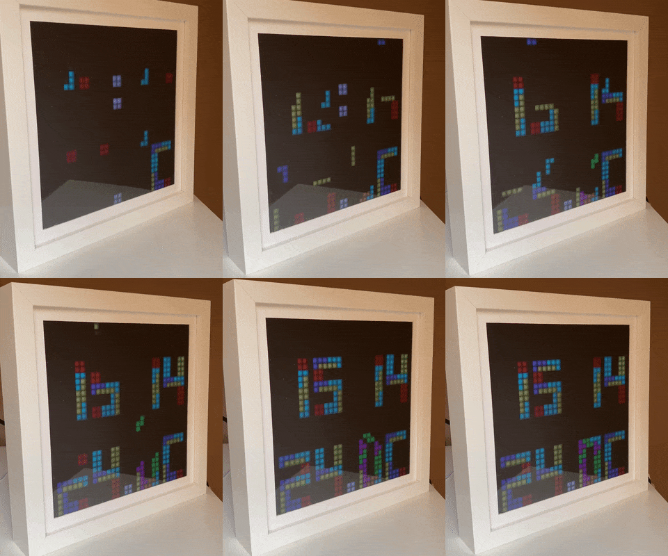
A tetris-style clock in a wooden frame. I built this using a RGB matrix driven by a ESP8266. I used @2dom's PxMatrix library to drive the matrix. On top of this I built the clock animations with NTP sync.

I had this RGB LED matrix lying around for a while. I used it with a arduino mega (works good but no easy internet connection) and raspberry pi (flexible, but a big overhead and long startup time). So I was looking for a better solution and I found it when I saw this article on hackaday: https://hackaday.com/2017/11/28/a-minimalist-weather-clock-with-a-unique-display/

Dominic Buchstaller built a neat library for the ESP8266 to drive these RGB LEDs matrices. So connecting to the internet for NTP sync is no problem anymore. It also boots up instantly and can be powered off without shutting the system down before.

I had the idea to build a NTP synced clock and was looking for a creative way to display the time using available colors. After some googling I found a monocrome version of the tetris clock in some china shops. So I decided to build something similar using colors.

  • 1 × RGB Matrix 32x16 From Adafruit or directly from china ​Please note: These matrices exist in different pitch sizes P10 means 10mm and results in 32x16 cm panels. The latest build is based on a P6 matrix that is roughly 20x10 cm in size.
  • 1 × ESP8266 Dev Board NodeMCU board style
  • 1 × Wood for the frame
  • 1 × 3D printed parts https://www.thingiverse.com/thing:2846368
  • 1 × Acrylic glass and one-way mirror foil

View all 8 components

  • New build with 32x32 matrix, Brians D1 matrix board and a temperature sensor

    Tobias Blum08/30/2020 at 13:56 0 comments

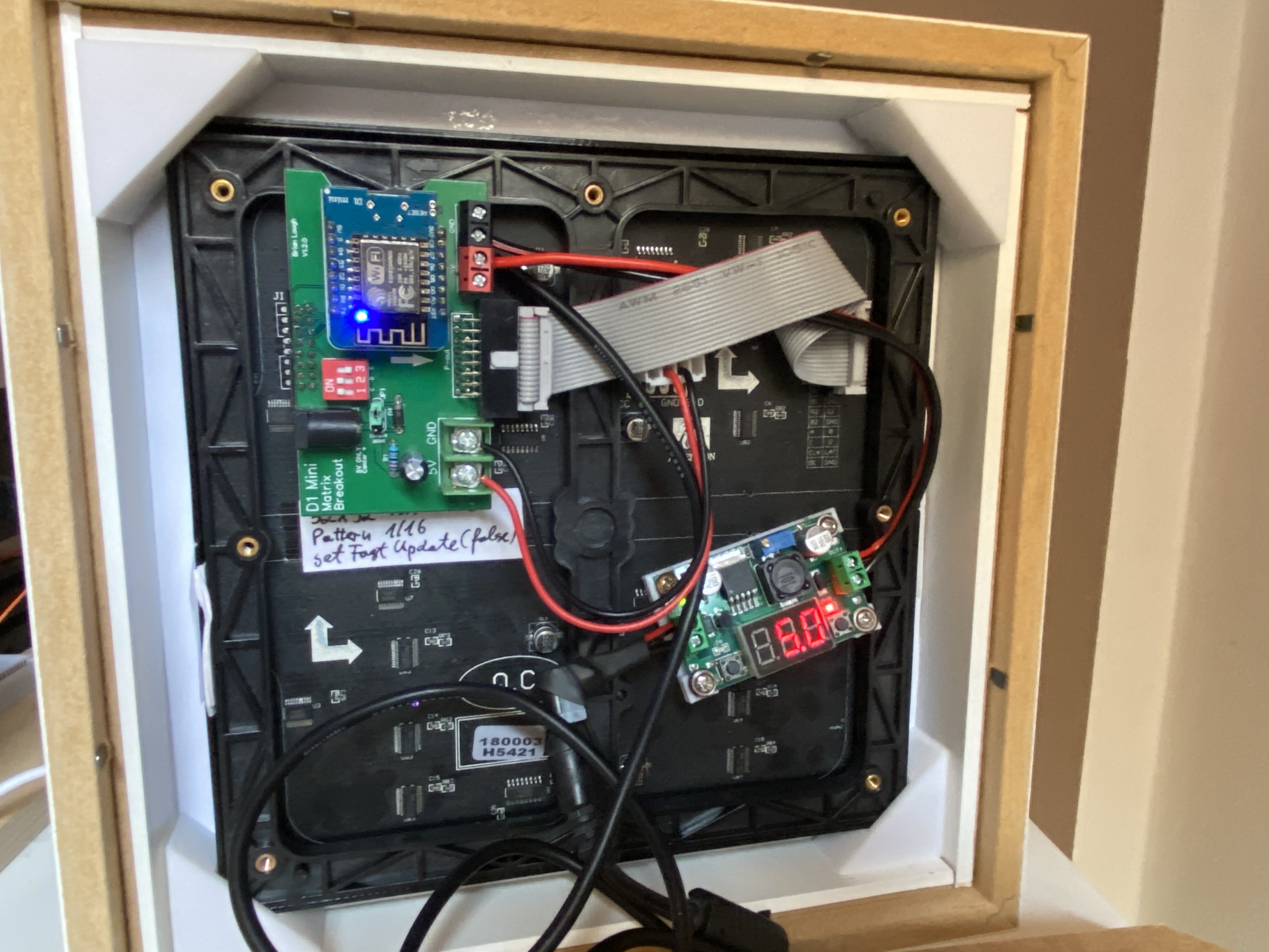
    Last month I built a new version with a 32x32 matrix that fits perfectly in a IKEA ribba frame.

    This time I used Brians Loughs D1 matrix board to optimize the cabling. Have a look at his boards if you like to build something similar: https://www.tindie.com/products/brianlough/d1-mini-matrix-shield/ 

    I updated the code to make it work with the recent versions of the libraries.

    This one is powered by a old 12V power supply and a LM2596 buck converter.

  • Flattening the matrix

    Tobias Blum04/15/2018 at 18:52 0 comments

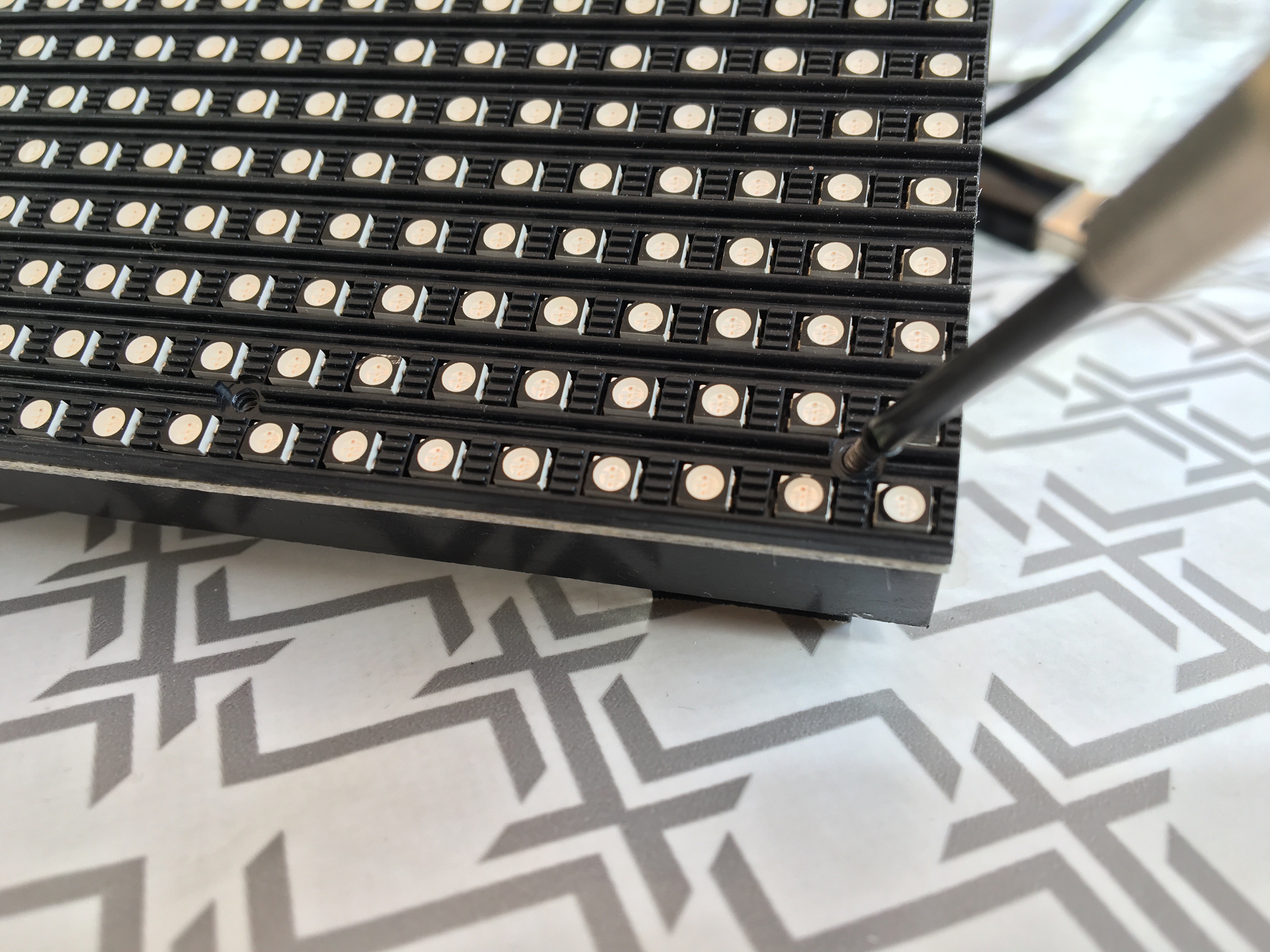
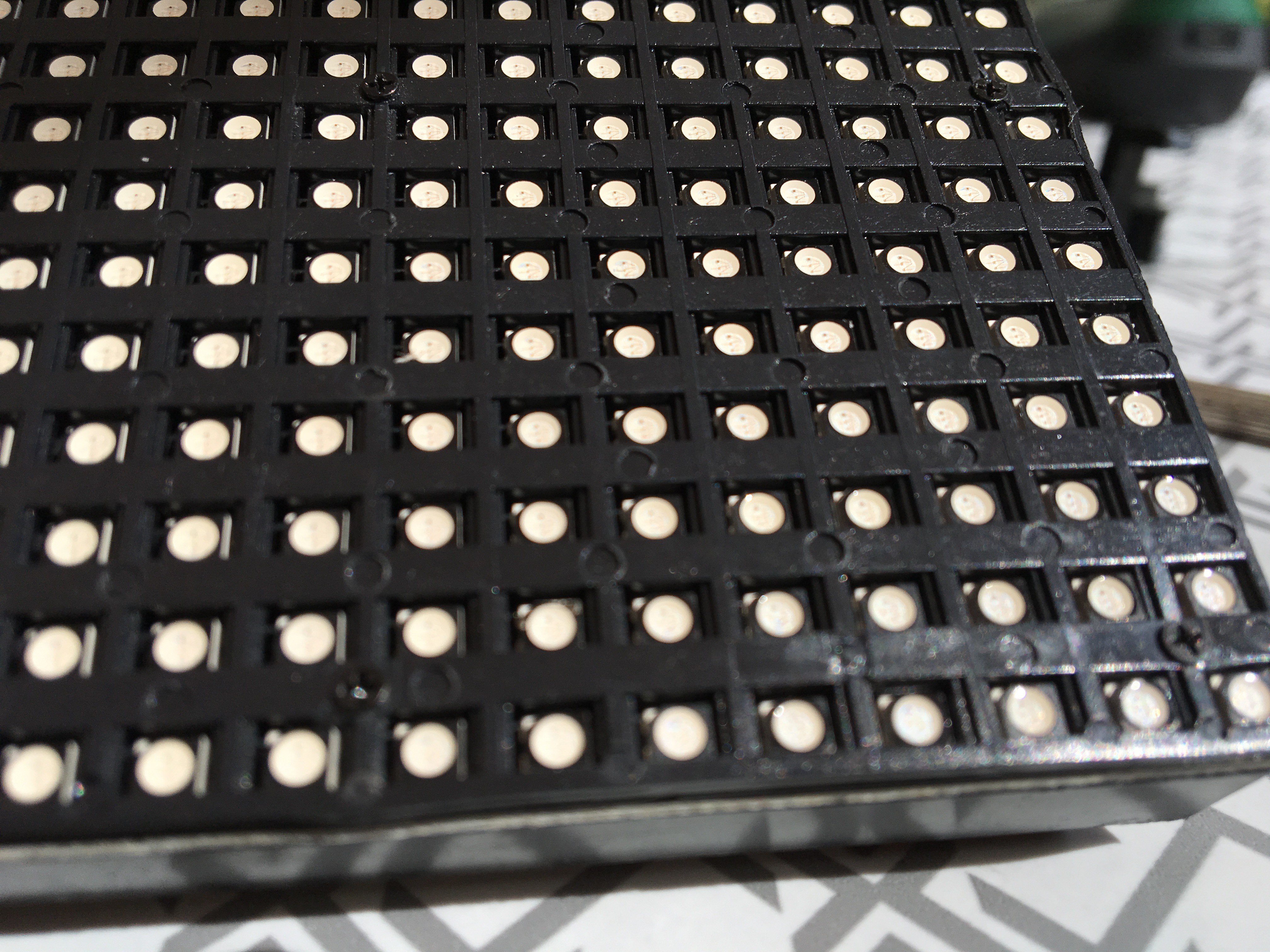
    In the first version I wasn't very happy with the clearness of the pixels. The matrix isn't flat, because the front plate has thin horizontal ridges the lat the light flow to neighbor pixels.

    Dominic Buchstaller gave me a hint:
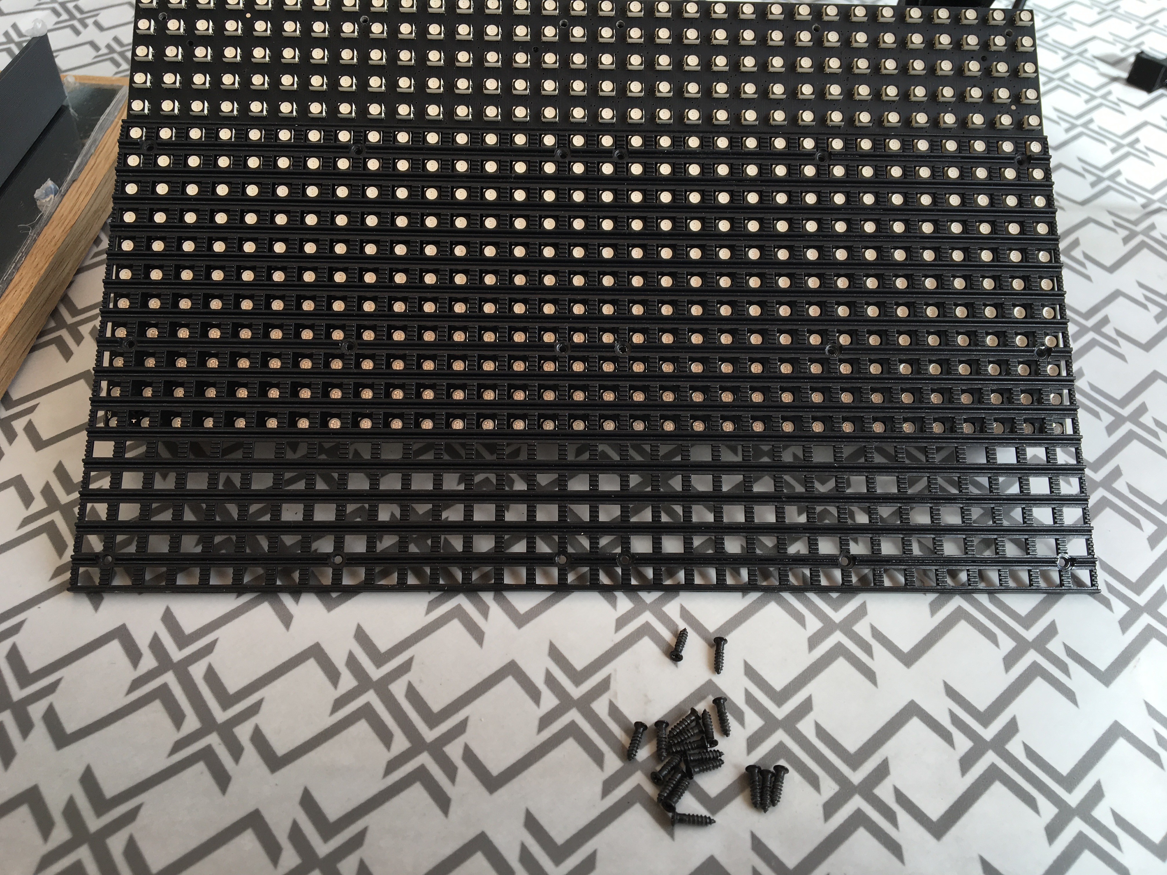
    You can loosen all the screws of the panels so that the front plate can be taken away. 

    Then you have two options:

    1. Leave the front plate and just rescrew the matrix. Then the LEDs fit nicely into the printed grid.
      The drawback is that you can't use a diffusor between matrix and printed grid.
    2. Turn the front plate around so that a flat surface is created and then resrcew it.
      I chose this option and it looks much better.

    Loosen the tiny screws:

    Take away the front plate:

    Turn and rescrew it:

View all 2 project logs

View all instructions

Enjoy this project?

Share

Discussions

Similar Projects

Does this project spark your interest?

Become a member to follow this project and never miss any updates