 Bradley Worley
There's a crick in my neck from staring at these monitors too long yesterday, but it's the necessary pain from re-working the entire PyPPM 2.1 design into a new set of schematics and board files: PyPPM 2.2!
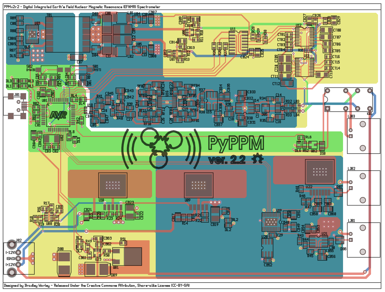
There are a few big changes and a smattering of subtle changes in the new design:
- Corrected -2.5V regulator pinout: I had screwed up the pinout on the adjustable version of the LT1964 low-noise regulator, and had to bodge in a fix on the PyPPM 2.1 board. This is fixed properly in the new design.
- Changed dual SD101A's to BAV199: The input protection diodes in the instrumentation amplifier section have been changed to lower-leakage, lower-Vf SOT23 parts to improve signal chain performance.
- Fixed part numbering scheme: This was driving me crazy, as I'd been continually adding and removing parts and renumbering in random ways. The parts now follow a logical ordering based on their appearance in the schematic.
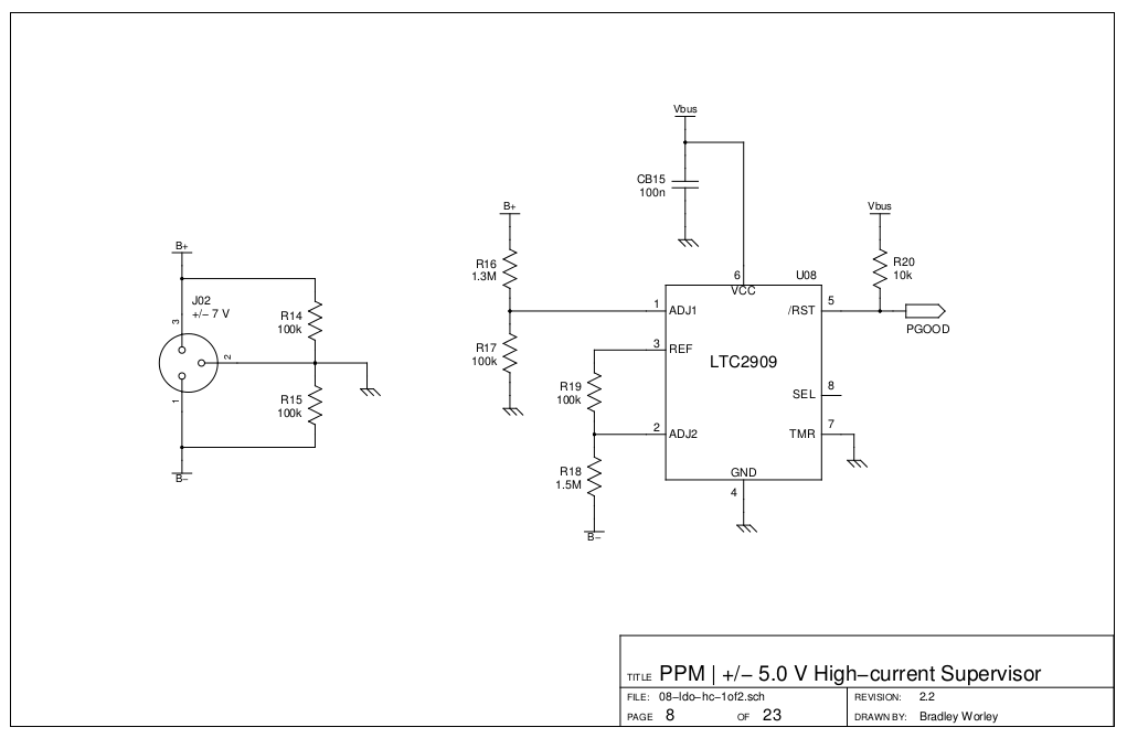
- Added +/- 5V rail supervisor: Now, the only way that the high-current +/- 5V regulators should start up is when (a) there is USB power and (b) there is at least +/- 7V applied to the regulator inputs. I was getting annoyed by the LT1763A "starting up" from leakage alone without an input voltage.
All the changes add up to a more robust hardware platform that's easier to build and maintain.
Oh! I also finally soldered everything onto the PyPPM 2.1 board:
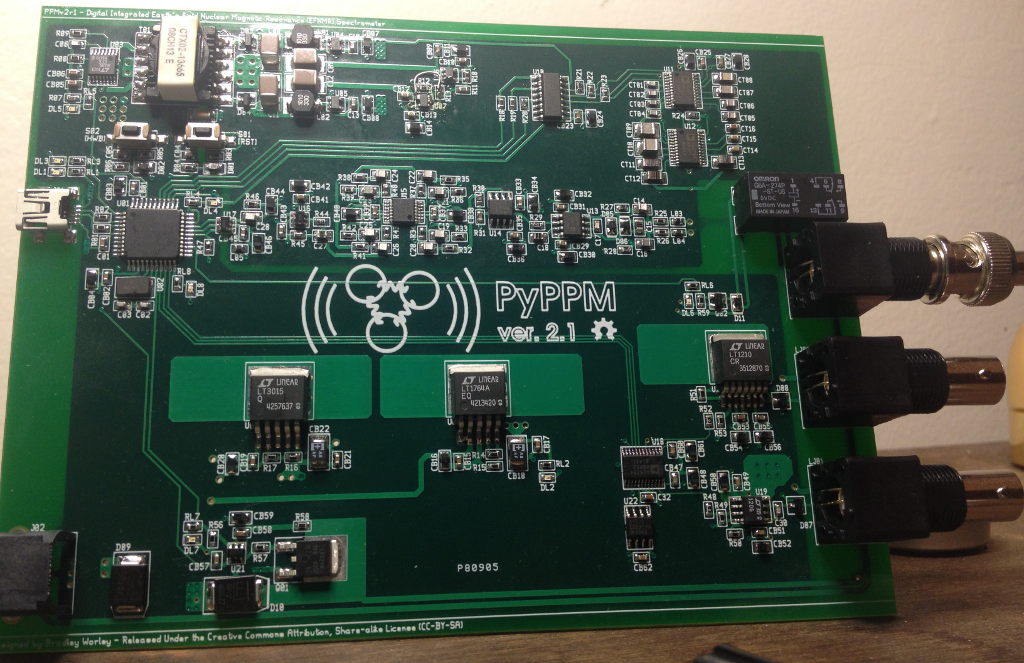
Isn't she pretty? :)
Discussions
Become a Hackaday.io Member
Create an account to leave a comment. Already have an account? Log In.