 Philip Ian Haasnoot
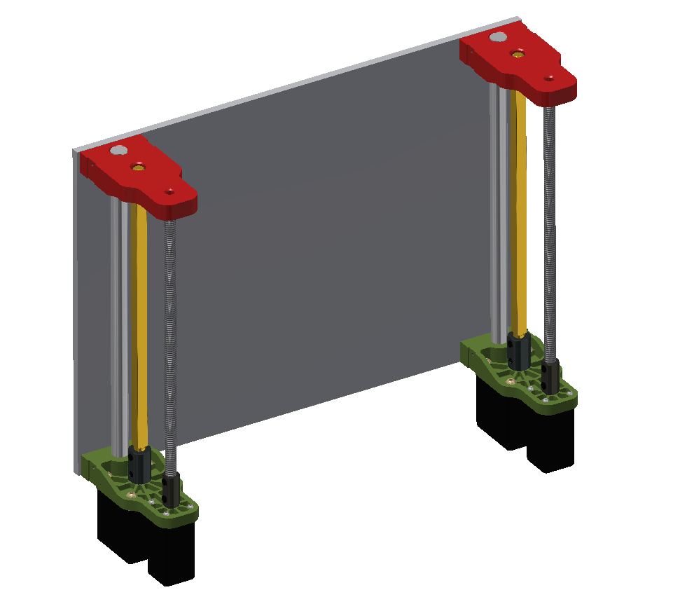
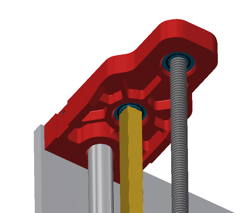
Tonight I was able to get some design work done for the top bearing block. This component houses two bearings, one for the square drive and the other for the lead screw. This block also constrains the top of the Z axis guide rod, and has a slot on each side to accommodate an IR proximity sensor for end stops.
In the close up you can see the slot and mounting hole designed to accommodate the Sparkfun QRE1113 breakout board. I choose to go with an off-the-shelf breakout to make this easier to manufacture for those who cannot spin their own PCB's.
Slots for the sensors have also been added to the lower motor mounts. Both the motor mounts and the upper bearing blocks are symmetrical to bring the overall cost down if this ends up going to a larger scale production (Twice the parts, lower price per part).
I am planning to get the Z-axis carriages designed tomorrow.
Discussions
Become a Hackaday.io Member
Create an account to leave a comment. Already have an account? Log In.