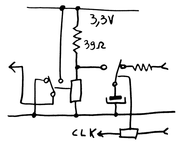
So that's another twist of this "exercice de style" : now it's time to evolve from the ring oscillator to the Linear Feedback Shift Register :-)
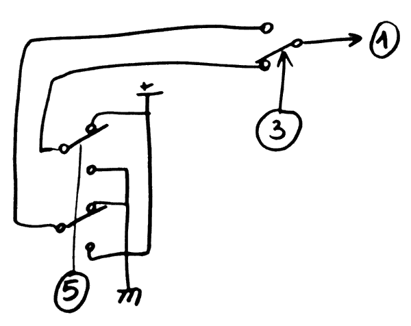
I'll start with a 5-tap LFSR with poly (5,3), meaning relay#1 gets the XOR of relay#3 and relay#5. This generates a cyclic sequence of 31 numbers, excluding the number 0.

It's time to evaluate how many relays are required: each "square" or tap is a synchronous FlipFlop, which uses 2 relays: one for storage, the other for clock/control. A capacitor is used as a temporary storage.

The little gotcha is the clock : at 5 tap, it doesn't work well to optimise the power, I can make 2 DPDT with 4 relays but another relay will need a bias resistor. Hopefully, this will be addressed in the final version, with an even number of taps (or multiple of 4 ?)

So far we have 2 relays per tap (10 SPDT relays for 5 taps) but the XOR2 is not done yet. This is solved with a "PBRL-DPDT" structure as shown in a previous log.
Tap#1 needs a single data input, which is XORed by tap#3, so an auxiliary relay (the second of the DPDT structure) selects one of two inputs. These inputs are generated by tap#5, which swaps +Vcc and 0V depending on its state.
This adds 2 relays so we get the formula 2(n+1) relays for n taps. I have not counted the MUX to the address bus though, so it's on the order of 3n.
Time to build it :-)
 Yann Guidon / YGDES
Discussions
Become a Hackaday.io Member
Create an account to leave a comment. Already have an account? Log In.