First, I needed to decide the basic geometry for the printer. I drew up a rough model and decided on a delta radius of 170mm and an arm length of 250mm. This would give enough reach and resolution to print on a standard 200mm x 200mm MK2B PCB heated bed. I did investigate a circular heated bed but the cost was significantly higher at the time.
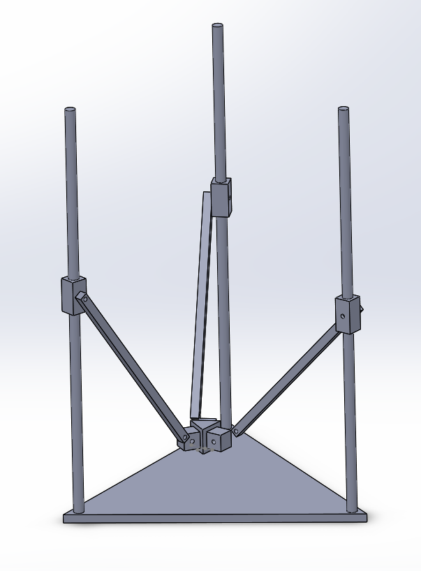
Geometry Design
My original design composed of top and bottom sheets of MDF or Aluminium with some 4040 extrusions as a frame. This would provide high rigidity and allow the use of thin linear rails.
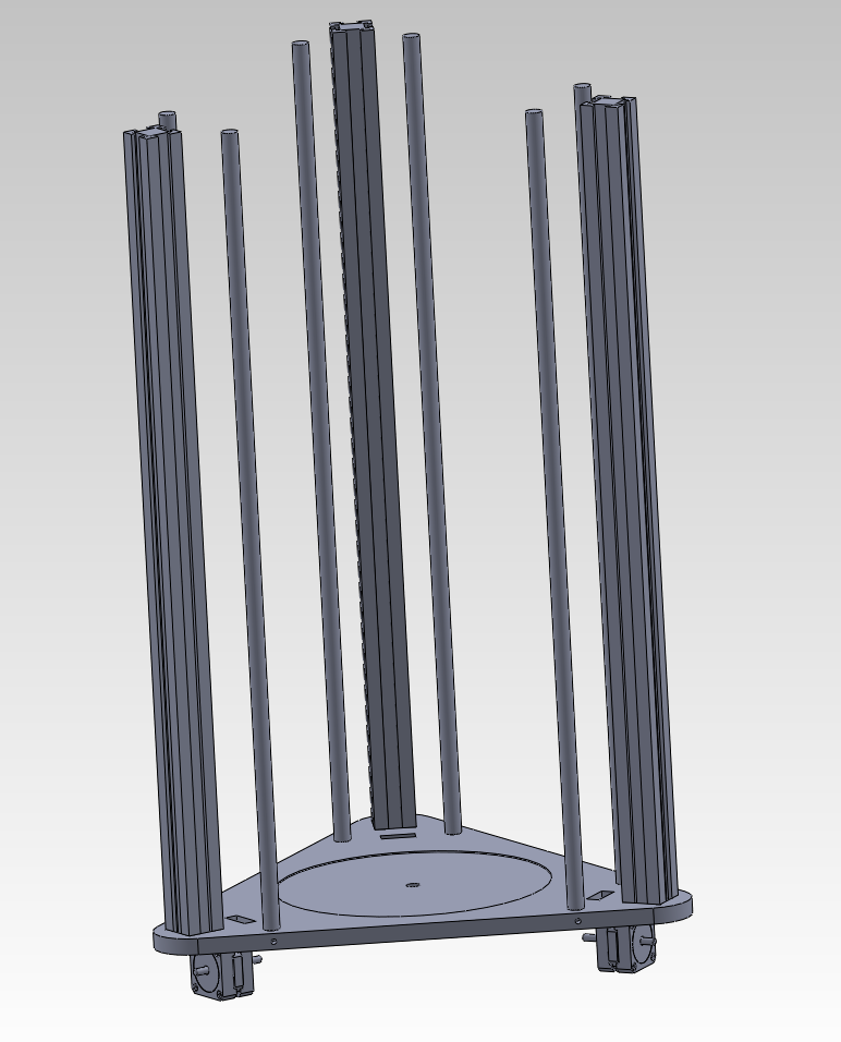
Printer V1
I decided I didn't like the design and started googling for
more ideas. I stumbled upon this:
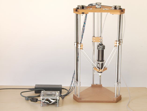
Source: http://www.3ders.org/articles/20130915-build-your-own-ceramic-delta-3d-printer.html
I found the printer in the above blog featured a very simple frame design. It consisted of wooden (MDF) frames top and bottom with linear rails performing both structural and functional roles. It used widely available LMxxUU bearings and simple RC car ball joints. This design was very simple and elegant. I found some 12mm shaft mounts on eBay and figured that they would help to hold the linear shafts in the MDF nicely.
My first ‘complete-ish’ design had the motors at the top. This was to minimise wiring going from the power/control circuitry down the sides of the printer. It had a few flaws that I didn’t like:
- There was nowhere to run the wires as the linear bearings needed clearance.
- The power supply would need to be at the top so the mains lead might get in the way.
- It would be quite top heavy.
- Rigidity would be a problem.
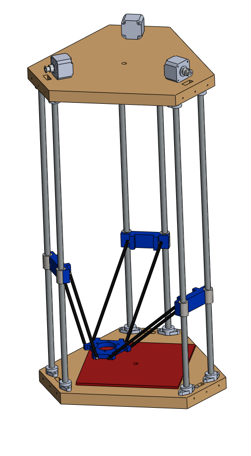
Printer V2
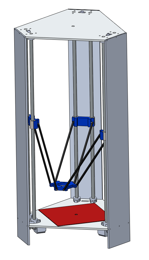
I had some thoughts that the frame might not be rigid enough as MDF can go soft when subjected to flexing (e.g. from transporting the printer). I changed my design a few times and ended up adding acrylic sheets to the sides. This would increase frame stiffness and give somewhere to run the wiring. I also decided to have the motors, power supply and control board tucked neatly underneath.
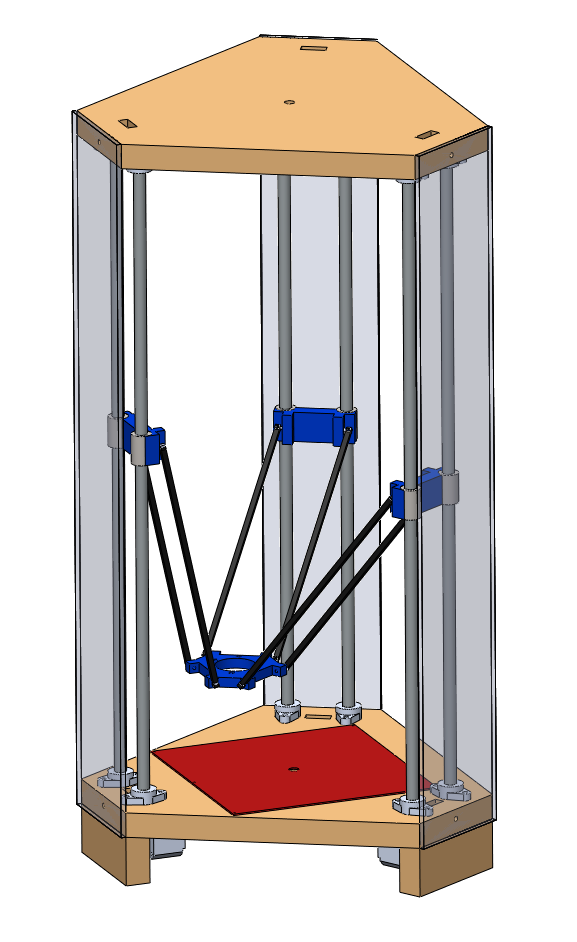
Printer V3
I had read many times that to achieve good accuracy, the
tower positions must be perfectly spaced.
I had planned to cut the MDF sheets by hand so decided that a jig would
be required for decent tower spacing.
Luckily, I had a friend who worked at a manufacturing house with a large
table router. I sent through my CAD file
and a few days later was holding on to a heavy 1/4” (6.35mm) sheet of CNC cut
aluminium.
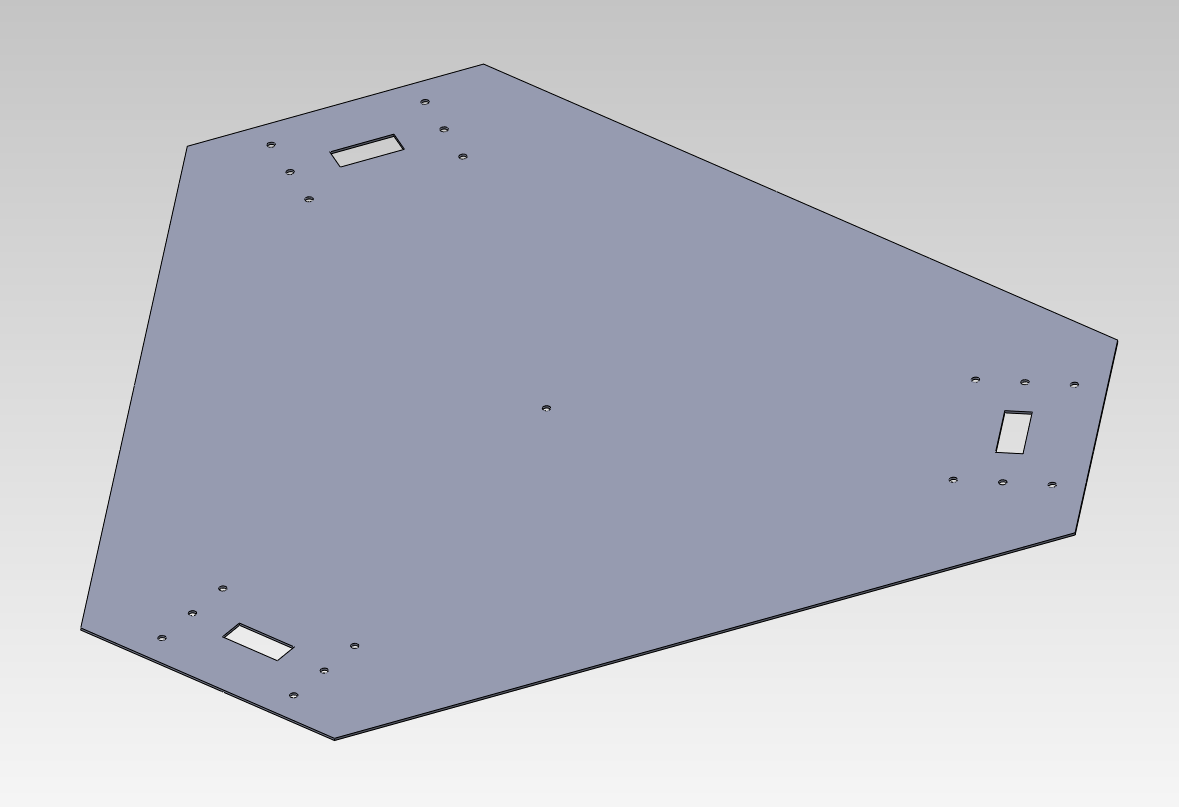
Drill Jig Design
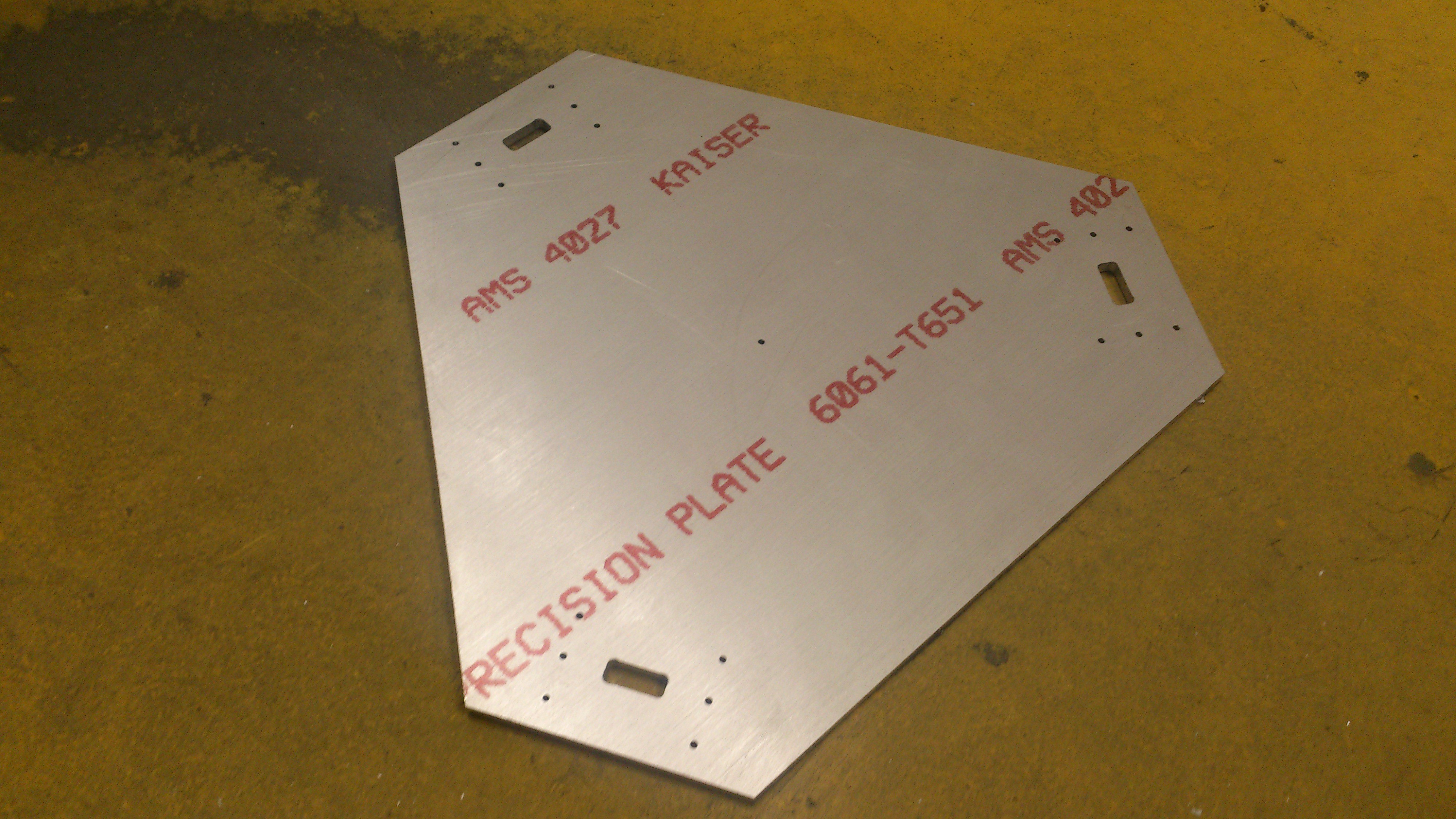
Hefty Drill Jig
I was expecting it to be thinner and I jokingly said to him that I “might as well use it as the frame instead” to which he replied “I can cut you another one tomorrow if you’d like, and any other bits you need”.
I excitedly said “yes” because aluminium would be much better than MDF. I then did another iteration of my CAD design with new side frames. The side frames would have a groove milled into them so that I was guaranteed that the frame would “pull true” when assembled. This design decision was fundamental in achieving a very straight and rigid frame. It ultimately resulted in an easy to calibrate printer.
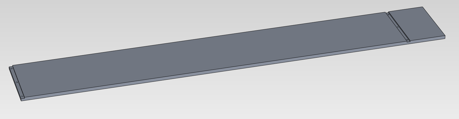
Side Frame
Printer V4
Due to the thickness of the aluminium sheet I planned to
drill and tap a number of M3 threads into the edge. The side frames would then be able to be
bolted straight to the top and bottom plates without the use of brackets. This would be a very neat and tidy solution and
hopefully strong enough.
Discussions
Become a Hackaday.io Member
Create an account to leave a comment. Already have an account? Log In.