I chose the RAMPS 1.4 board because that was the most accessible controller at the time (Q1 2014). The Marlin firmware was mature and had a huge user base. It also had good support for delta configurations. I planned to install the control board, power supply and axis motors underneath the bottom plate. This kept most of the wiring down the bottom. I would still need to run wiring up to the top for the endstops and any wiring to go to the end effector. Some printers have the bowden tube and wiring attached about half way up one of the towers. Whilst this keeps the bowden tube short for good retraction/ooze characteristics, it meant that I would have the extruder hanging off the side of one of the towers. This didn’t align with my design goal of having everything inside the triangular footprint of the printer. I decided that the extruder would be attached underneath the top plate and the Bowden tube would run down from there. Some small ducting ran up the inside of the rear (Z axis) tower and then cables would run alongside the bowden tube from the top (with the aid of spiral cable wrap).
I had not received my power supply yet but had my battery charger supply (12V 30A) available. I knew the approximate dimensions so tried to allow for it when mounting the RAMPS board. I was really happy with the decision to use aluminium plate as drilling and tapping M3 holes everywhere was super easy and very secure to mount things to.
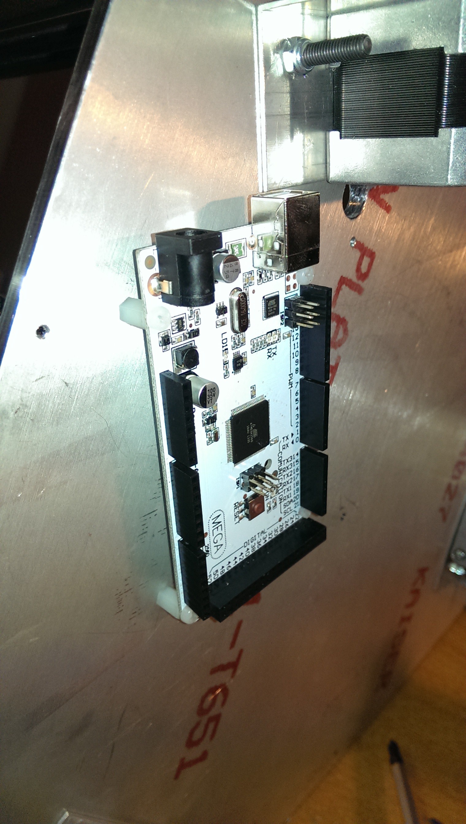
Nylon standoffs in tapped M3 holes
I had a few spare computer fans lying around and thought it would be a good idea to actively cool the controller. I’d read that the stepper motor drivers could get quite hot and would benefit from active cooling. It was simple to tap a few more holes and add some more nylon standoffs to mount a fan.
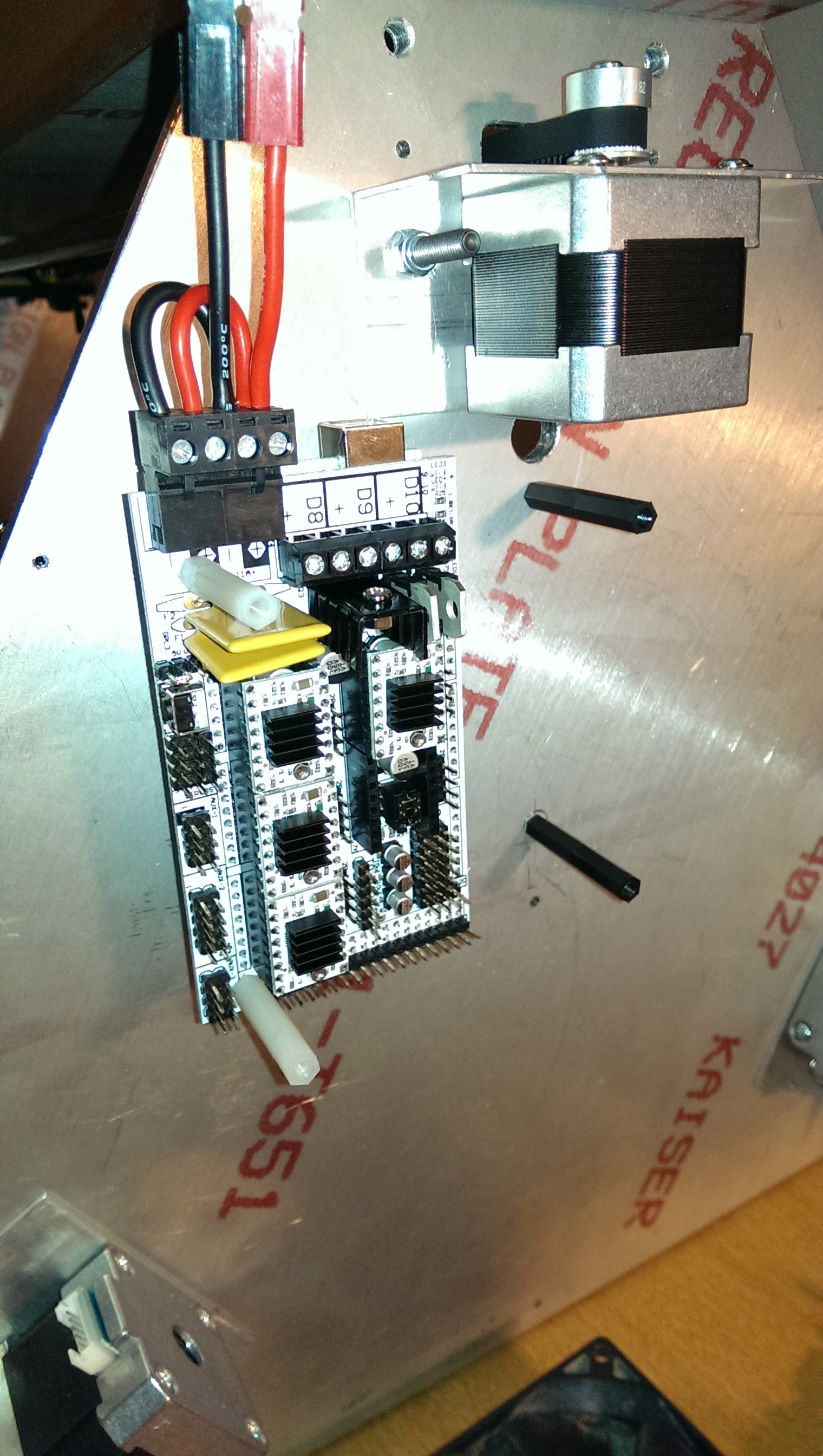
Standoffs
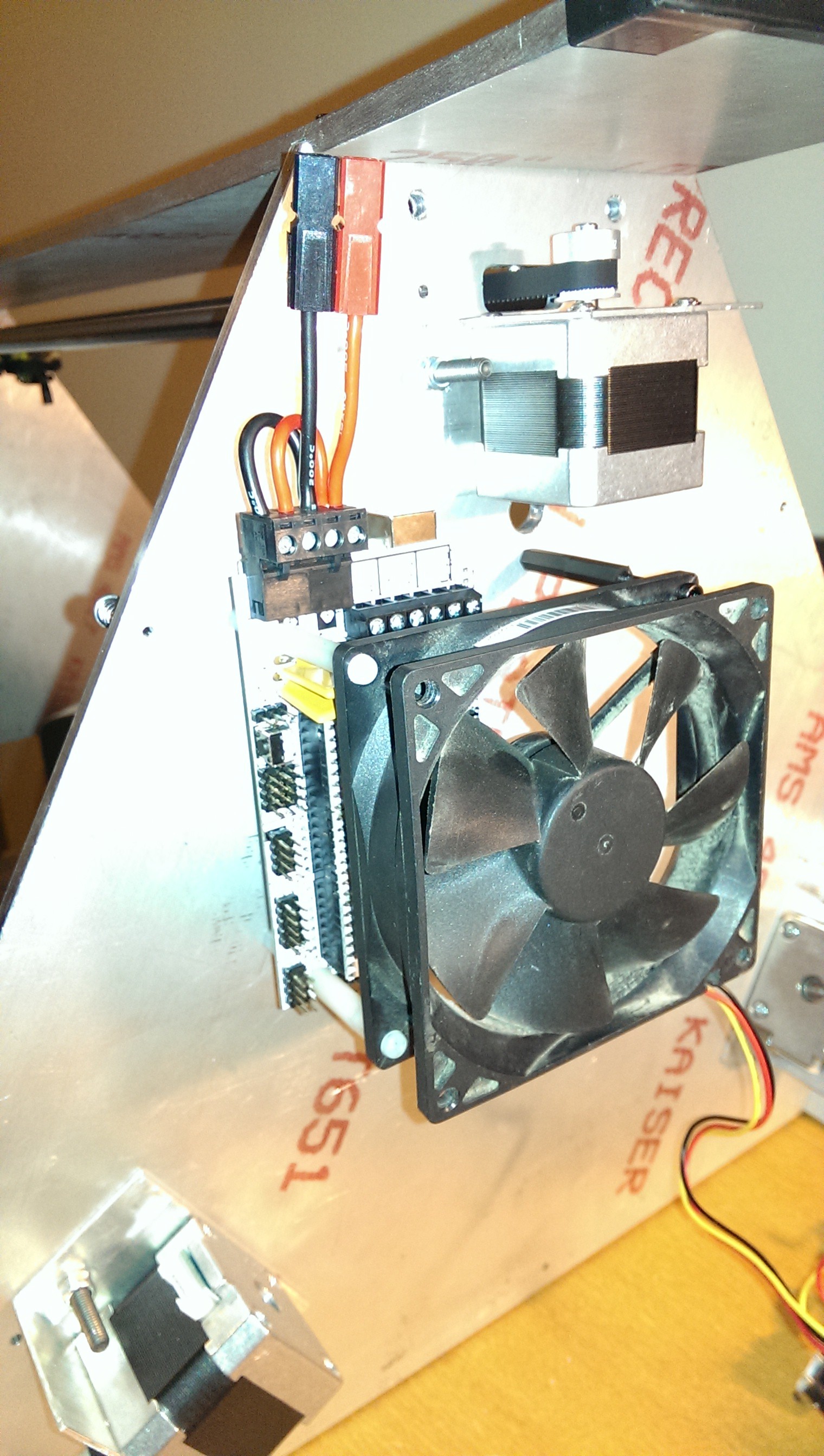
Cooling fan
The electronics kit from LearCNC came with heaps of pre-terminated wiring. I was able to use most of the provided wires and easily extended some of them for the further away items. The picture below shows most of the bottom wiring complete. I had some spare Anderson connectors lying around. These would be used to connect to the temporary power supply and later to the “integrated” power supply.
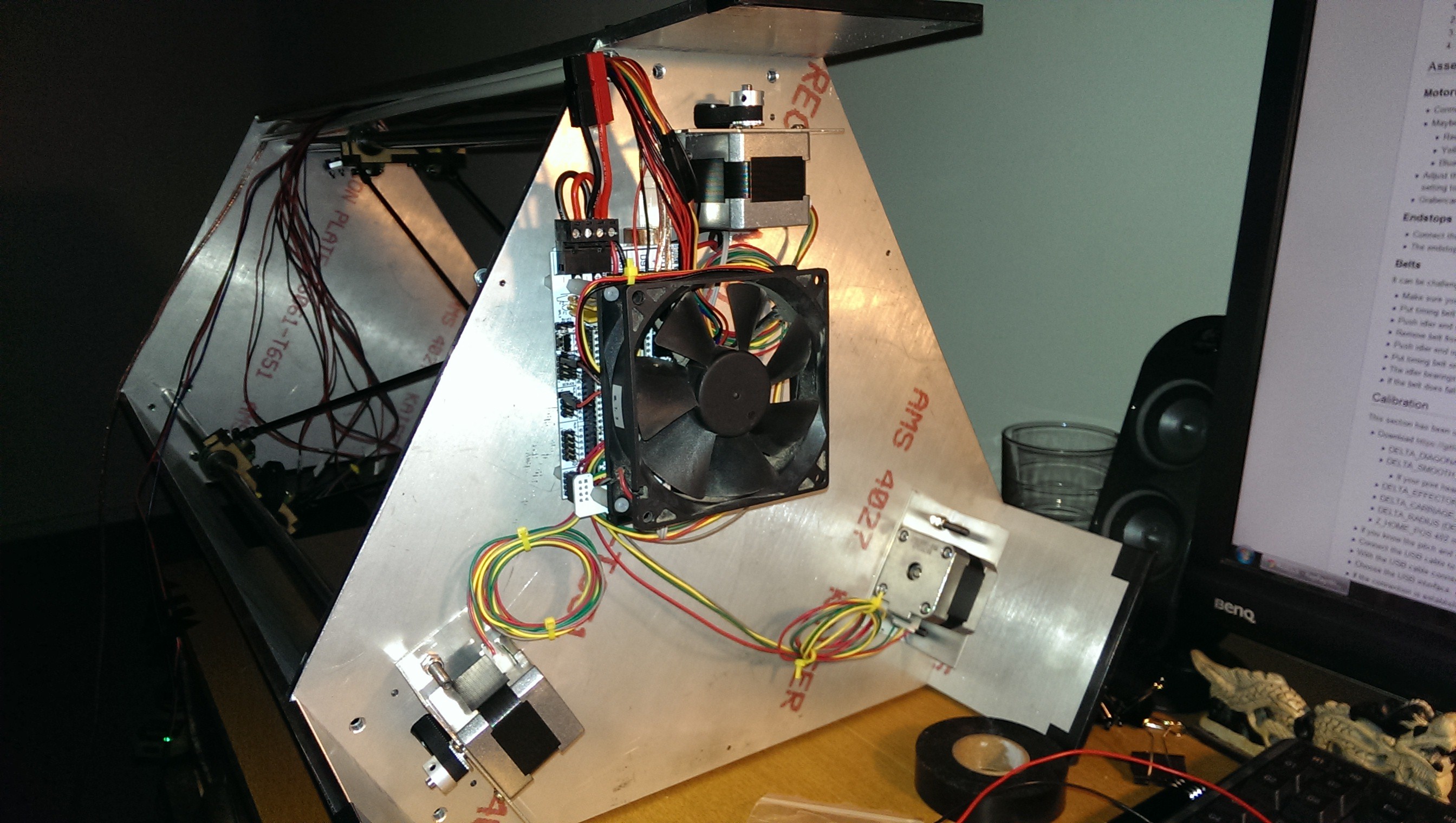
Wiring is half way there
I ran the ducting all the way up to where I had mounted the extruder. Wires could then be cable tied to the start of the Bowden tube. In the picture below you can also see the three JR style plugs for the endstops. Endstops will be discussed in a later section.

Wire routing
I originally wanted to have automatic bed levelling (tramming) and included a simple servo mounted micro switch. I ended up removing it because Marlin firmware didn’t have bed levelling for delta printers implemented yet. I ran some extra cables down to the hot end for an “always on” fan.
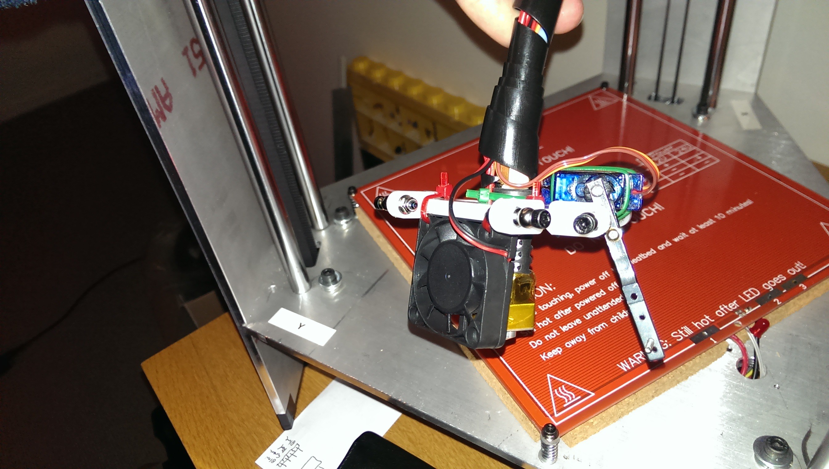
Extruder cooling fan
Discussions
Become a Hackaday.io Member
Create an account to leave a comment. Already have an account? Log In.