Since this is the first project log, I'll 'briefly' go over the motor and driver as I tear it down.
With the inverter lid popped off it's a bit clearer where the actual motor is. (it's smaller than the inverter!!)
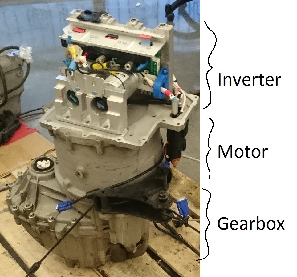
in that picture I've already removed the gate drive board.
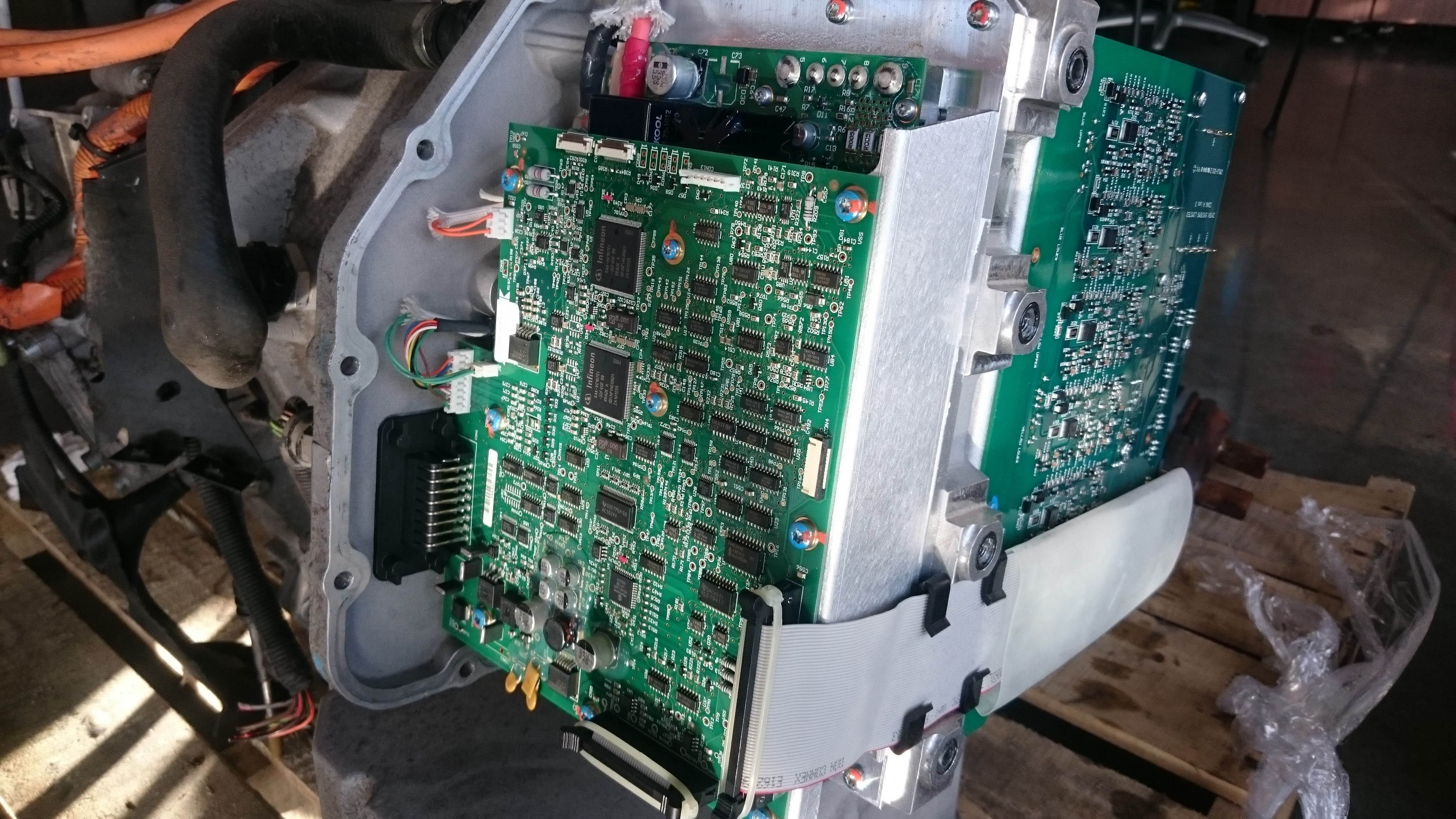
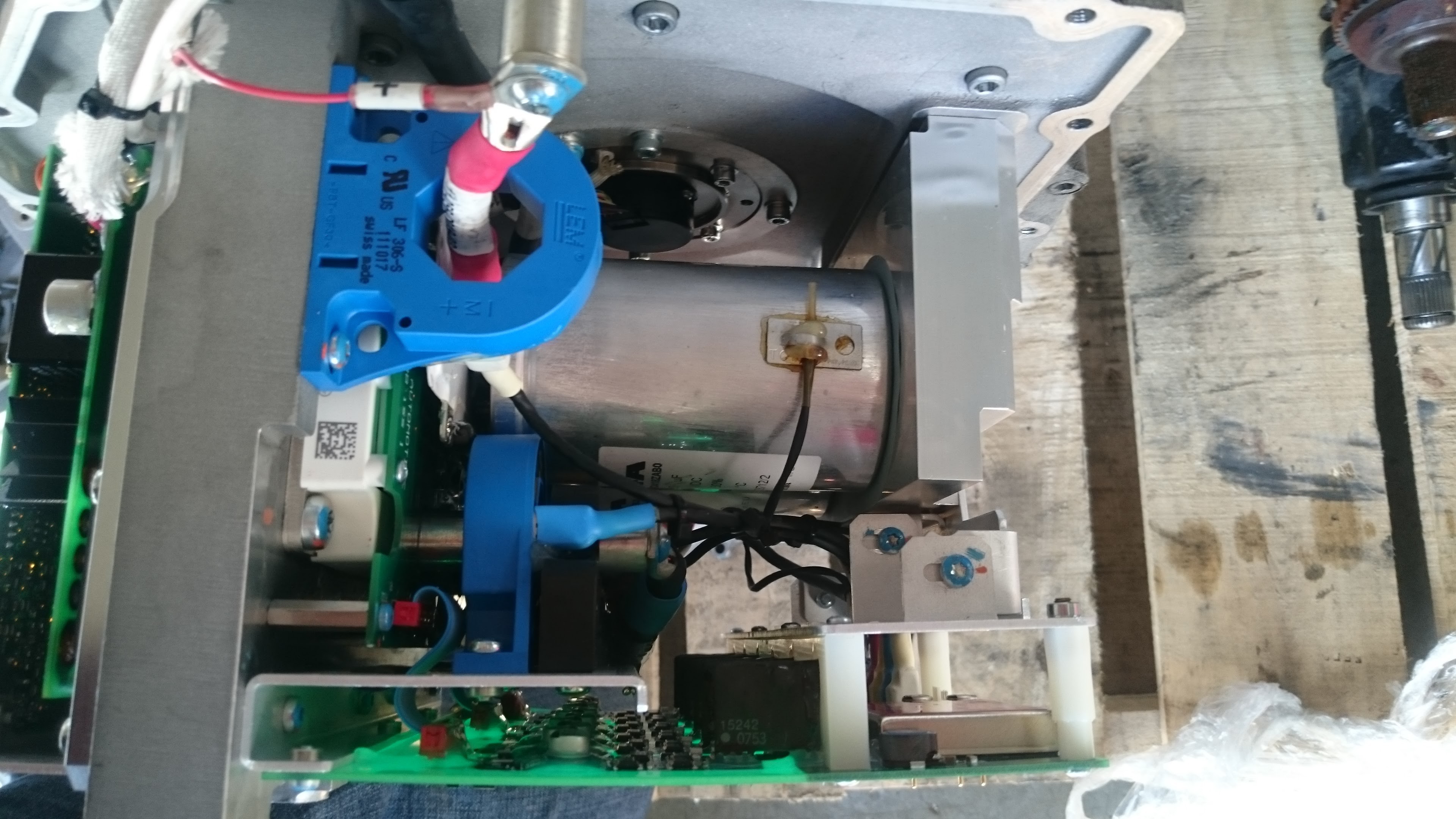
A couple of better closeups of the inverter layout:
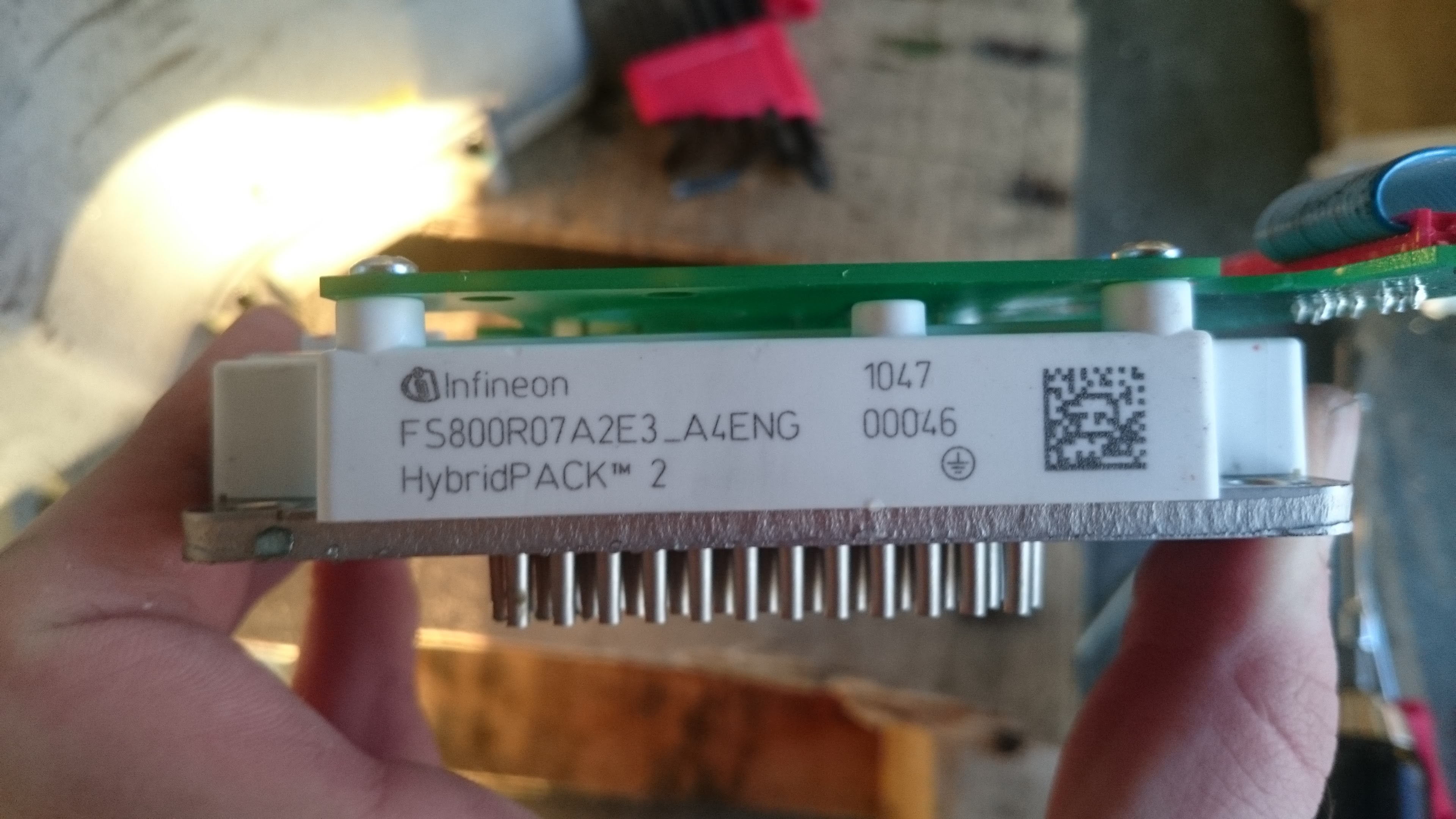
The inverter (called so because it takes DC from the battery and generates a 3-phase AC current) consists of various PCBs for controlling the main insulated-gate bipolar transistor (IGBT) module:
This module is an arrangement of 6 transistors, two on each motor phase. the 'highside' transistor connects the motor phase to the positive terminal of the battery, the low side connects it to the negative. The high side and low side are turned on periodically (NEVER at the same time as this would short out the battery) at 10khz with an average 50% duty cycle. by controlling the duty cycle of each phase, the motor can be provided with the required AC signal and driven in any direction with controllable speed and torque. The inductance of the motor (about 170uH) provides some electrical filtering which limits the current ripple through the switches.
Two 1800uH 450V capacitors filter the current spikes on the input DC bus. They are mounted to a heatsink and have thermal sensors, so they clearly get hot. Which is no surprise given they are electrolytic caps, and would be very lossy at 10khz. kinda funny design choice there. I'll go on a rant about the 10khz switching frequency in a later post...
To properly control the torque, a current feedback loop is required, a current transformer (the blue ring things) on each motor phase plus one on the battery terminal are used (4 total.) These transformers are also able to measure DC current as they combine both a transformer winding and hall effect sensor.
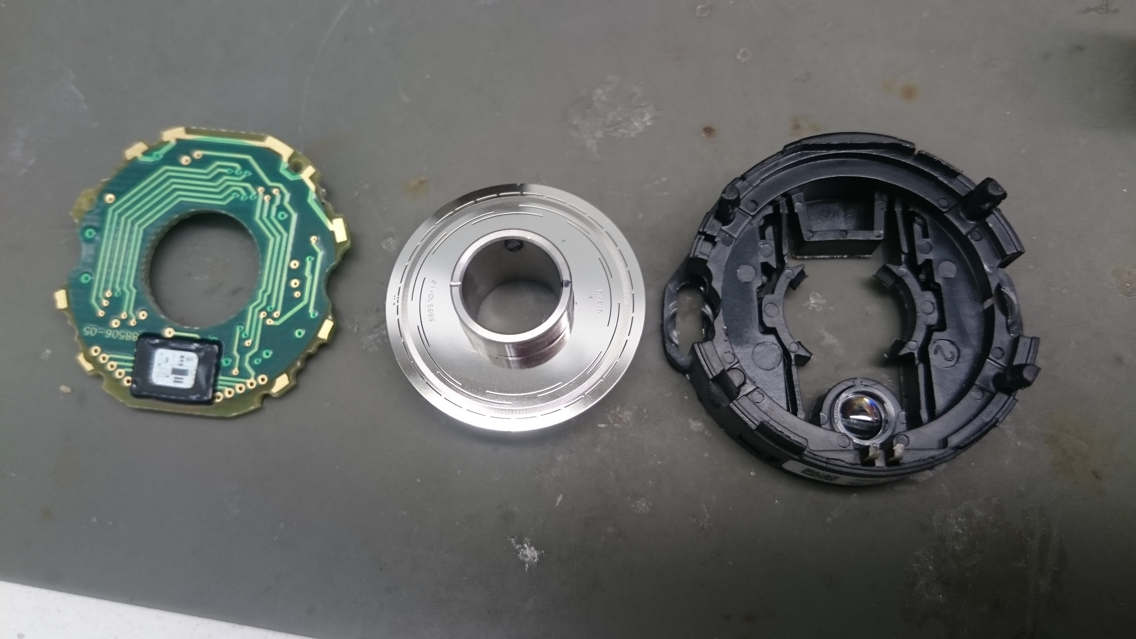
The generation of AC waveforms must by synchronized with the motor rotation, this is done with an optical shaft encoder, a pretty cool little device in it's self. It contains a stainless steel disk with tiny holes cut in it, this acts as a photo-interrupter with an LED on one side of the disk and a small photo-sensor IC on the other. The encoder outputs a tachometer pulse, a six-step signal (same as you get out of the three Hall sensors on a common BLDC motor) plus a high-resolution quadrature signal (hundreds of steps per electrical period)
The electronics are actually powered from the car 12V battery system (which also powers the cars lights and aux systems and is connected to the car chassis) so for safety the high voltage 200-400VDC battery connected circuit must be isolated from the 12V system, so all gate drive and sense circuits need to use optocouplers or transformers to achieve isolation and transmit power. The inverter also contains a couple of 400V->12V DC-DC modules which use transformers for isolated power to charge the 12V battery system.
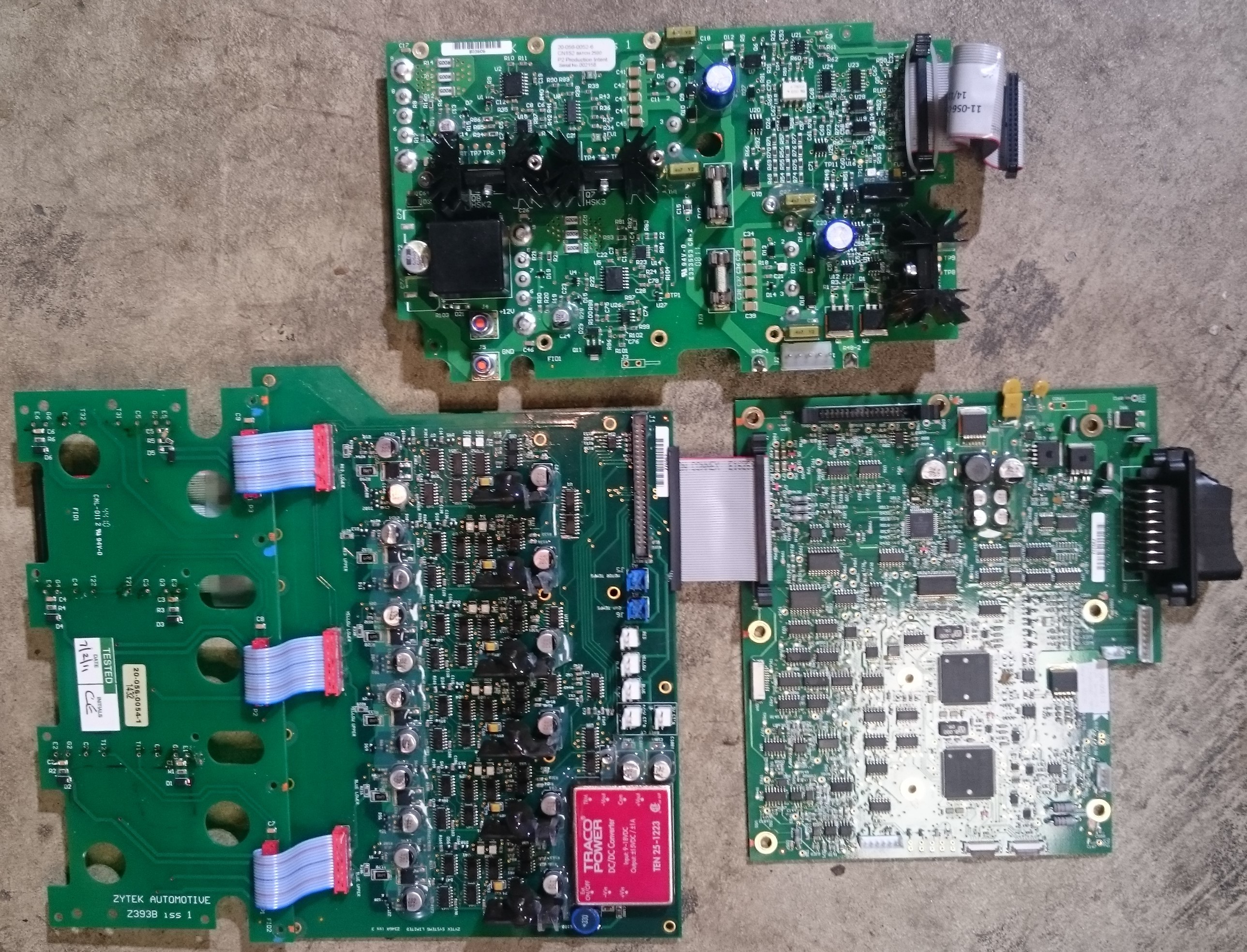
The circuits are split between 4 PCBs:
Top is the 400V-12V DC/DC board (heatsunk power modules are below the PCB) left is the board that mounts on the IGBT module, connected to it is the gate drive board which has 6 identical driver circuits, each one with an isolated +15/-5V power supply and optocouplers for signalling. It also contains some logic to prevent both switches turning on at the same time (called shoot-through protection or deadtime as it also ensures a time where both switches are off) The current sensors also connect to this board, so it has a +/- 15V power supply to power these.
Lastly, the control board is on the right. it contains a PIC microcontroller I assume for monitoring circuit operation and two big Infineon microcontrollers, these clearly generate the motor control signals. They connect to the dual CAN bus and run in parallel for redundancy. A bunch of logic on the left of the board stitches the signals together and will presumably shut down the inverter in case of a contention between the two controllers. The board also contains analog circuitry for the current and thermal sensors, a 5V power supply, 12V switches (to enable/disable the other boards) and some other miscellaneous logic.
This control board is what I aim to replace!
Might as well post some pics of the motor internals too. It's a huge 'inrunner' type with a permanent magnet rotor and steel laminate stator. The stator and windings are encapsulated in epoxy and conduct waste heat to the motor casing which contains coolant channels to carry the heat away.
Rotor and encapsulated stator exposed after removing the inverter side: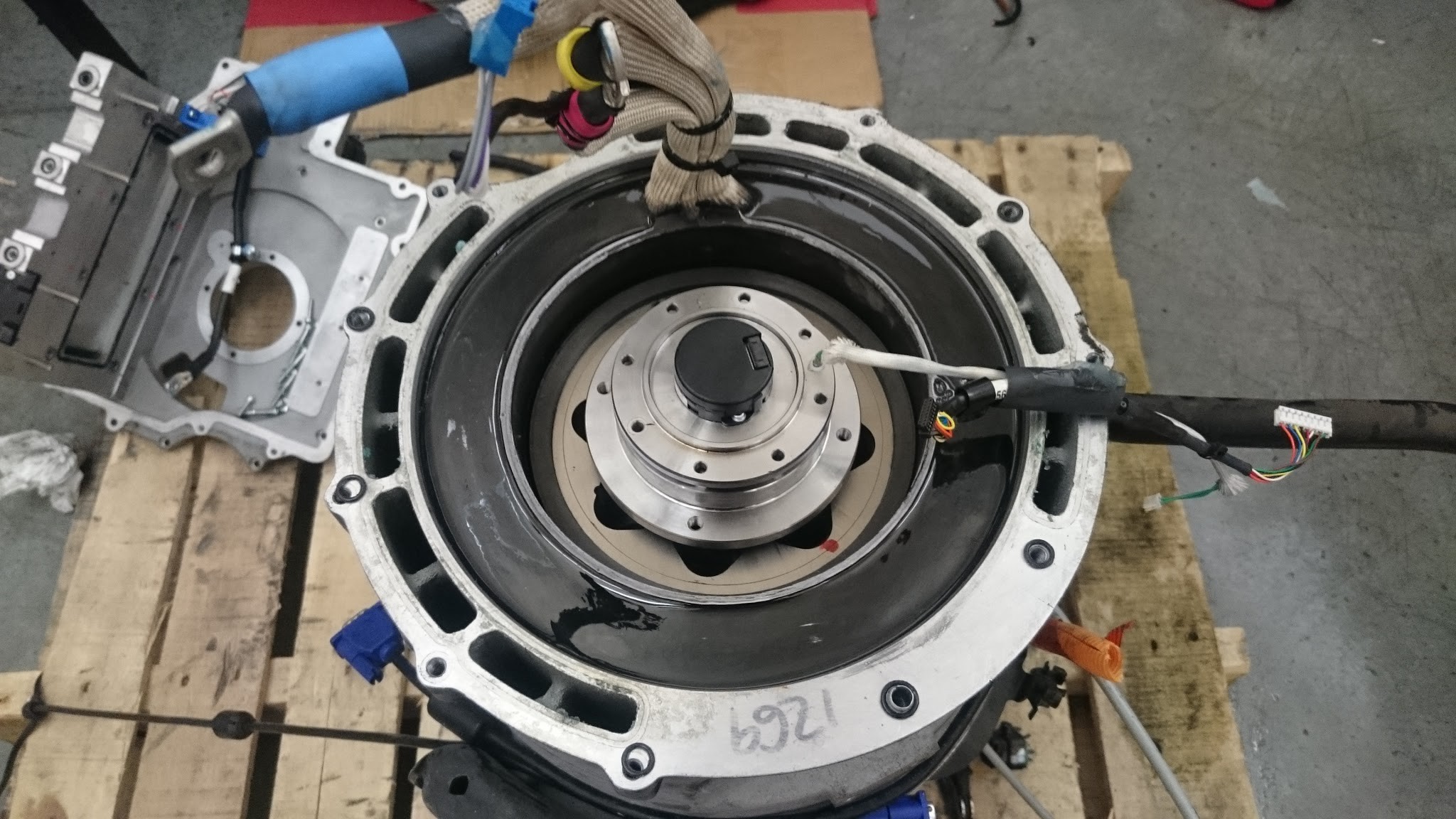
Can also see the water channels around the outer diameter, the sealed bearing and it's machined holder is still attached to the shaft, as is the shaft encoder. Motor wires can be seen protruding from the top.
The rotor removed from stator:
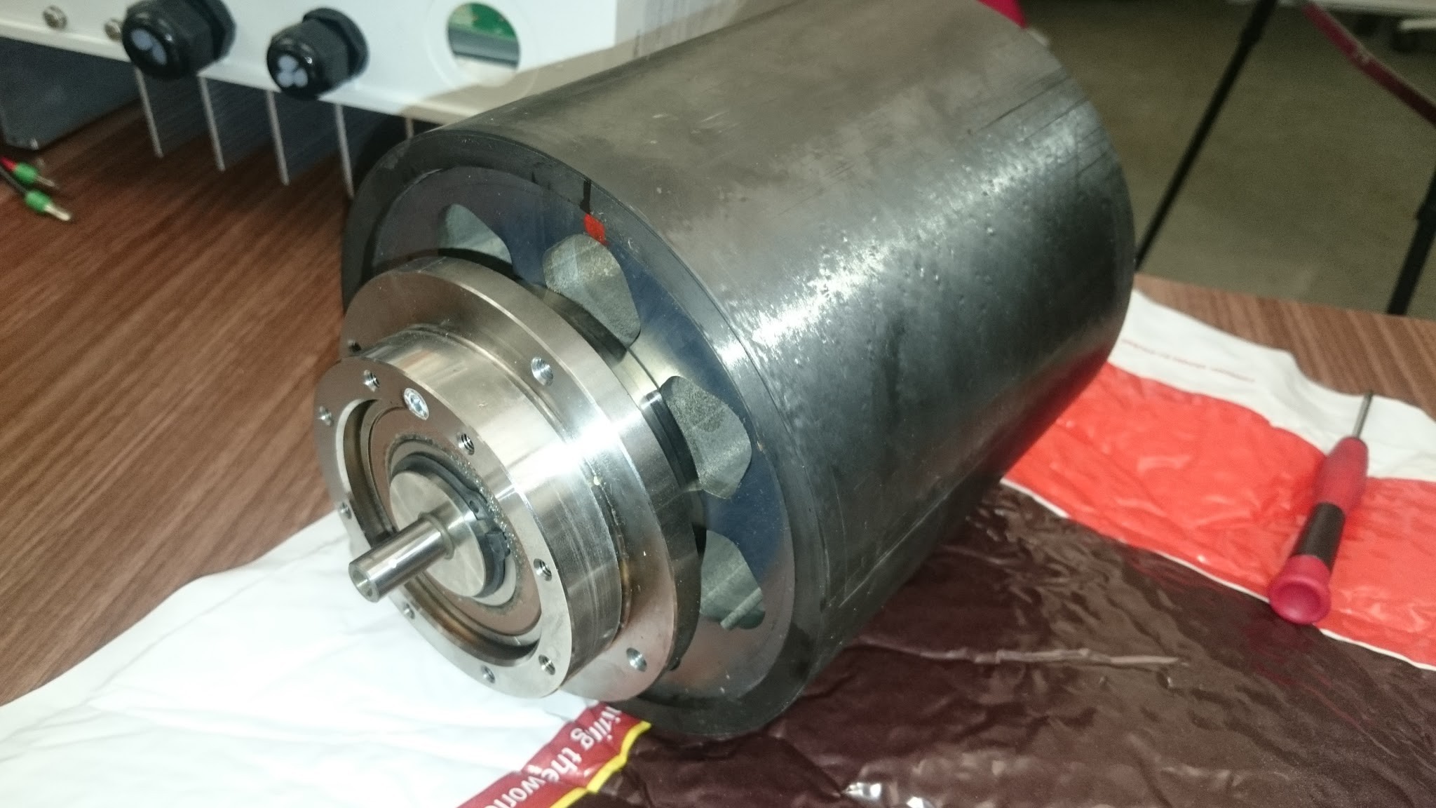
No small feat given it's got some pretty strong magnets, and really doesn't want to leave the low reluctance path of the stator. also its damn heavy! Can see the steel laminates that complete the reluctance path inside the rotor. I believe the actual magnets are around the diameter. There appears to be a carbon fiber coating to hold it all together.
And the stator with rotor removed:
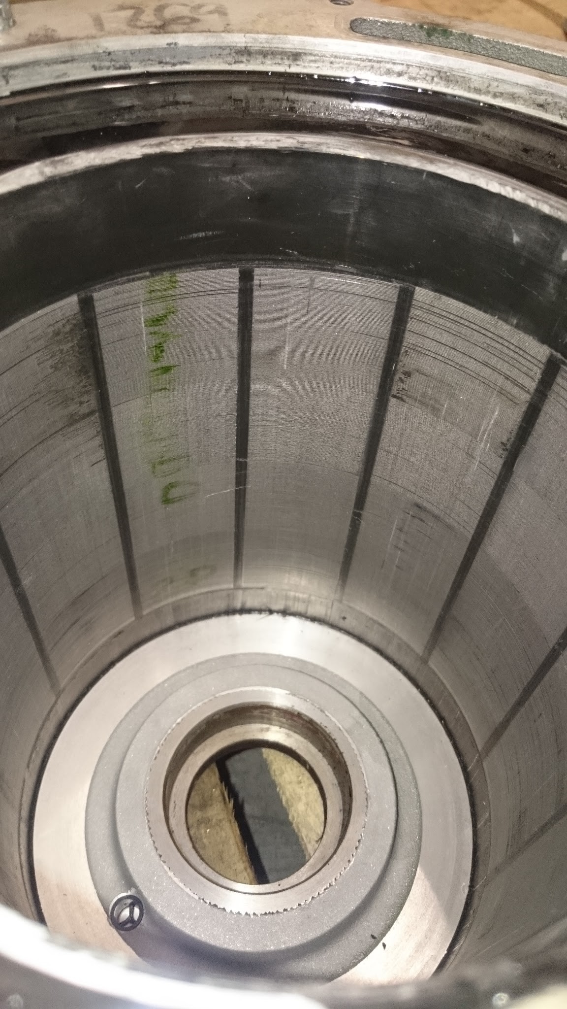
It's a 12 pole stator so has 4 electrical cycles per motor rotation.
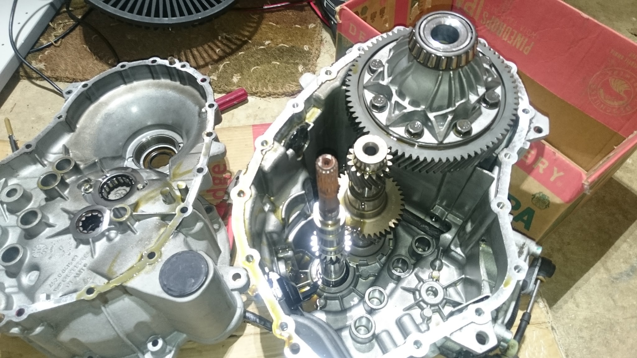
Finally the gearbox is a funny contraption. it's obviously a re-purposed manual transmission as there is a lot of empty space in there. it's got a fixed 8.75:1 ratio and built in differential.
 Jarrod
Discussions
Become a Hackaday.io Member
Create an account to leave a comment. Already have an account? Log In.