AT89
Most of Atmel FLASH x51 devices do have ISP capability, carried over SPI interface. That's the easy part. However, communication protocol is not exactly the same, greatly complicating programmer's software.
I bought those parts: AT89S52, AT89S8253, AT89LP52, AT89LP51RB2, AT89LS52, AT89LP4052, AT89S2051 and AT89LP6440 and while browsing datasheets of those MCU I found out that there are virtually no two identical parts, when it comes to programming protocol.
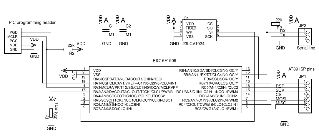
Programming hardware
It is quite simple. One low-end PIC and serial SPI RAM. I decided to use external RAM because binary image of target memory could be quite huge (up to 64kB) and inernal RAM would be not sufficient. There is possibility of using MCU with more internal RAM, but those are made with 3,3V IO, so level converters would be needed. Writing FLASH of the target on the fly is possible, but due to different programming times and page size granularity for different MCUs it would need careful timing and selection of serial baud rate, so I opted for external RAM instead. The image is loaded into external SRAM and then handled as needed.
As I did it in my STK500 project, whole thing is powered from target supply, operating in 3-5V range, so no level converters are needed. However, user has to be careful, as there is no overvoltage protection, so every mistake could be dangerous for programmer.
Working with programmer
It may seem to be a bit counter-intuitive, but once you get used to it, it's simple. There are only single letter commands (with no line end, only one ASCII character).
h: print help
a: toggle auto mode on(erasing-flashing target after receiving HEX file) or off
p: toggle page sizes - 1B/32B/64B
t: check target signature
b: list buffer content
r: list target memory content
e: erase target memory content
w: program target memory with buffer content
v: verify target memory against buffer content
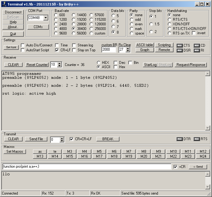
l: toggle 89LP mode (mode 0 - no preamble, suitable for 89S52, 89S8253, 89LP52; mode 1 - 1 byte preamble, suitable for 89S2051; mode 2 - 2 byte preamble, suitable for 89LP51RB2, 89LP6440) Using l mode other than 0 keeps page size to 32B regardless of p setting.
o: toggle reset logic (0 - active high, 1 - active low)
Default reset values are: a - 1 (target is erased/flashed/verified after receiving HEX file into external RAM buffer), p - 1B (single byte write), o - 0 (reset is active high), l - 0 (no preamble mode).
For example, working with AT89LP6440 needs setting to active high reset and 2 byte preamble mode, so after starting the programmer
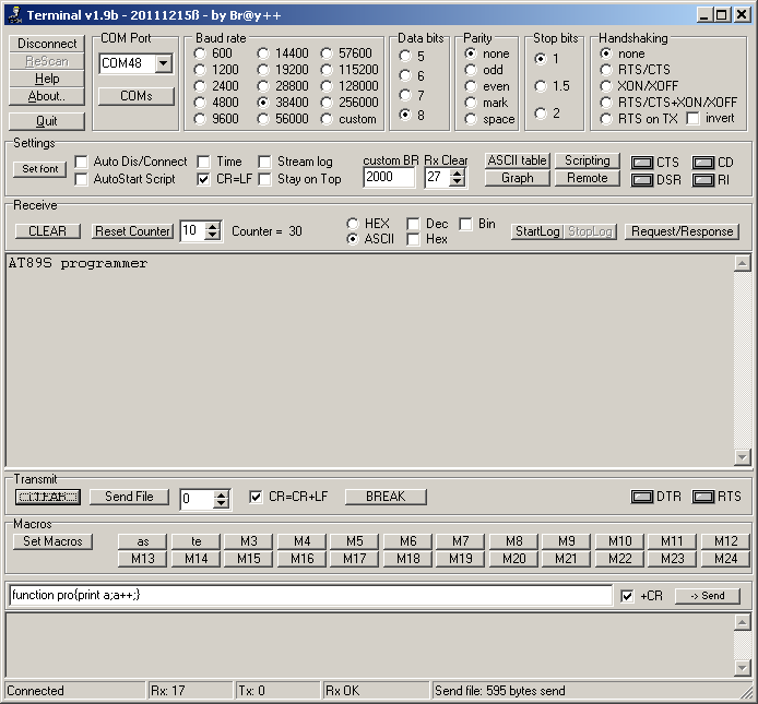
user needs to enter l twice (to toogle into mode 1 and 2) and o once (toggle reset polarity).
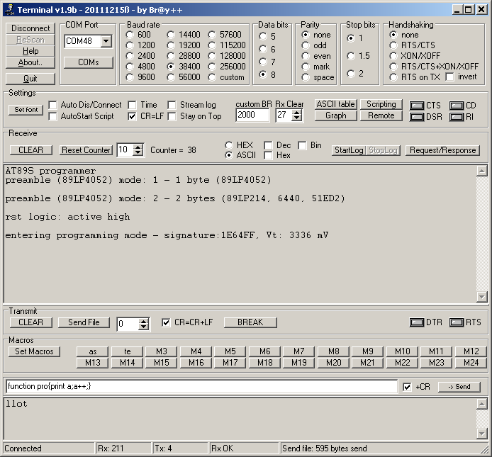
Then, t should perform target test and print its signature.
If everything is OK, programmer is set for programming session and ready to accept HEX file (Send file function or just copy file into tty device).
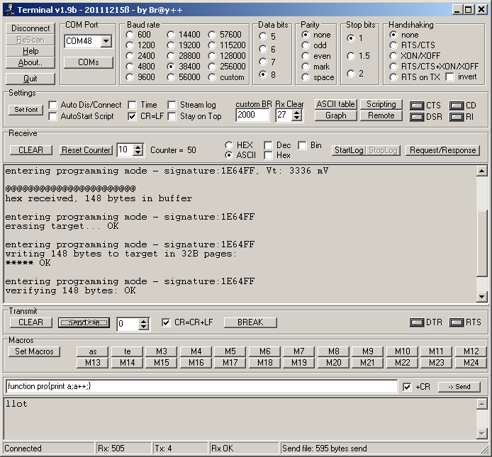
Setting table for MCUs I programmed
| MCU | l | p | o |
| AT89S51/52 | 0 | 1 | 0 |
| AT89S8253 | 0 | 32 | 0 |
| AT89S2051/4051 | 0 | 32 | 0 |
| AT89LP2052/4052 | 1 | x | 0 |
| AT89LS52 | 0 | 1 | 0 |
| AT89LP52 | 0 | 1 | 0 |
| AT89LP6440 | 2 | x | 1 |
| AT89LP51RB2/RC2/IC2 | 2 | x | 0 |
Conclusion
AT89C MCUs are not that attractive nowadays and this programmer is more designer's joke than serious tool, but after all, it works as expected.
Note that fuse and lock bit programming is not yet supported.
 jaromir.sukuba
Discussions
Become a Hackaday.io Member
Create an account to leave a comment. Already have an account? Log In.