I have finished the PCB design and ordered a first batch, so here is a quick update about it.
In short, the requirements for the PCB were:
- Shaped and sized to stack on top of the manifold, using two standoffs
- Connectors: USB, i2c, analog in/out, power, and an ICSP programming header
- Support for either SPI or Analog versions of Honeywell pressure sensors, as well as enough space for the sensor and tubing connecting it to the manifold
- 2 proportional solenoid valve drivers, with support for various voltages (5-24V at least)
Essentially, I want a small, integrated package, but still offer as much flexibility as possible with regards to communication with other components, and choice of valves and sensors.
The manifold I wrote about in the last log measures 45x45mm. The PCB should fit inside that, minus a couple millimeters on each side to allow space for an enclosure. This leaves little space for the components, so I had to pack everything in quite tightly and minimize the number of components on the board.
For the microcontroller, I chose an ATMega32u4, since it is Arduino-compatible (the Arduino Leonardo is an ATMega32u4), and it has built-in USB support. I wanted Arduino compatibility not only to make programming easier, but also to make the PCB design as easy as possible. I don't have any experience in designing boards for microcontrollers, so this way I could simply re-use elements of the Arduino Leonardo, Sparkfun Pro Micro, etc.
For the communication between the pressure regulator and external microcontrollers or computers, I wanted an i2c interface as well as USB (which would be used both to control the regulator and to program it if necessary). I also thought it would be good to include a simple analog input and output, where the set point and process values are given as voltages.
As explained in a previous log, I went with Honeywell pressure sensors. They are expensive (~30$/pc) but they are very precise and require no external amplifiers. They simply report the current pressure over SPI or i2c, or as an analog voltage between 0 and 3.3V or 5V. I wanted to support at least the SPI and analog variants.
There are also a bunch of different footprints for these sensors, but the most common one is an 8 pin DIP package. There was no easy way to use the same pins for both variants, so I simply put the two footprints side-by-side. One set of pins is used for the analog sensor, and the other set of pins is used for the SPI sensor.
I chose to go with a 3.3V operating voltage, for easier integration with other microcontrollers over i2c, since basically everything nowadays runs on 3.3V. To interface with a 5V microcontroller, one would need either a level shifter (for i2c), or a simple voltage divider for the analog set point.
The main constraints on the design were the shape of the manifold (square, with two cutouts in opposite corners), the placement of the pressure sensor, and the relatively large number of connectors (for such a small PCB).
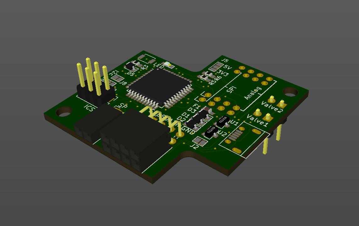
I did end up managing to fit everything onto a 2-layer PCB, cramming components on both sides of the board. Here's what it looks like:

On the bottom-right, you can see the connectors for the valves. These are pointed downwards, as the board will be stacked above them. If all goes well, there should be enough room for the connectors and cables, although it will be a snug fit.
Just to left of these are the pins for the pressure sensors. Either an SPI or analog sensor can be used, depending on which pins they are connected to. There is also a jumper to supply either 3.3V or 5V to the sensor, specifically for the analog model. I was not able to support both 3.3V and 5V SPI sensors, as this would require level shifters and I was out of board space.
In the bottom/left of the board are the connectors. The main one is a 4x2 connector, with pins for SDA, SCL, Vin and GND. They are doubled up to make it easy to daisy-chain several pressure regulators. The input voltage must be the solenoid's supply voltage -- anything from 5 to 24V should work just fine. Regulators bring this down to 3.3V and 5V for the rest of the board.
The other connector, 2x1, is the analog set point and current pressure. It will be possible to use either the analog or digital interface; switching between the two will likely be handled in software, with the analog being the default and switching over to i2c if a command is received there.
Also, it will be possible to set the i2c address via two jumpers: this should make it easy to change the address (between 4 pre-programmed options) without having to reflash the microcontroller. It's something I wish more i2c peripherals would do, since it can be handicapping to be limited to the factory-set address.
The 3x2 male header is the ICSP header, which will make it possible to flash the Arduino bootloader onto the atmega.
That's most of it, so I will stop here and patiently wait for my PCBs to arrive, and update when the boards are assembled!
 Craig Watson
Discussions
Become a Hackaday.io Member
Create an account to leave a comment. Already have an account? Log In.