 danjovic
After failing with using the internal oscillator I have switched to Arduino Board as a prototyping platform.
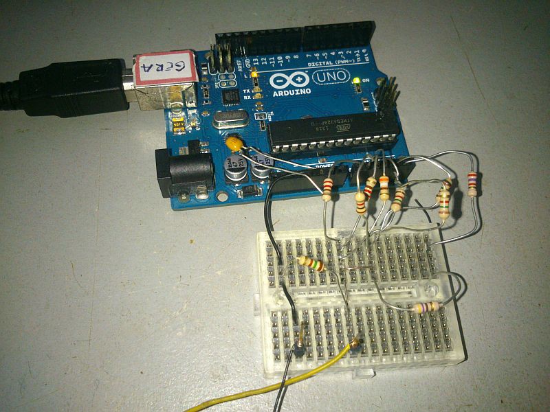
First thing noticed is that the image is perfectly stable using the crystal.
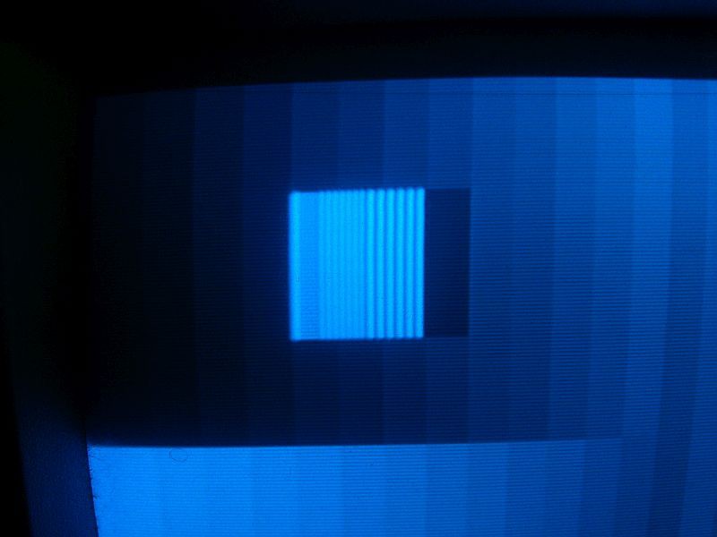
The correction of the grayscale shades after the resolution test pattern were another story. I needed a spare clock cycle to add 3 to the color pointer, then it was necessary to move one instruction some memory positions before and thus save a cycle. some tweak is still necessary, though to get the correct stripe colour after the resolution line pairs.
I have produced a spreadsheet that can calculate all the resistors based on values of VOH, VOL and the sync voltage level when the 75ohm load is attached (e.g. 0,15V). I have a good link on how to solve a matrix equation with rectangular matrices using standard functions of a modern spreadsheet program. No Scilab necessary!
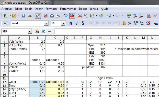
The spreadsheet resulted some values and I have used the most close value available in my parts bin. HOWEVER, I have noticed that the value for the resistors on most significant bits are somewhat critical.
for instance the calculated and used values were:
| Resistor | Calculated (Ohms) | Used (Ohms) |
| R Sync | 211 | 220 |
| R Bit 4 | 195 | 220 |
| R Bit 3 | 390 | 390 |
| R Bit 2 | 781 | 750 (1k5//1k5) |
| R Bit 1 | 1563 | 1K5 |
| R Bit 0 | 3131 | 3170 (2k7+470) |
| R Pulldown | 187 | 150 |
I have lost some time trying to figure out why I couldn't have a good linear (progressive) gradiend after the middle of the screen, and finally discovered that I should have used a value closer to 190 Ohm than the 220 Ohm I have used. At the end I have put another resistor in parallel so the equivalent resistance dropped to 180 Ohms (1k//220) and finally get a good gradient!
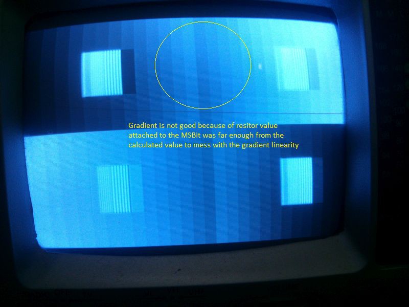
The image with correct resistor value can be seen below
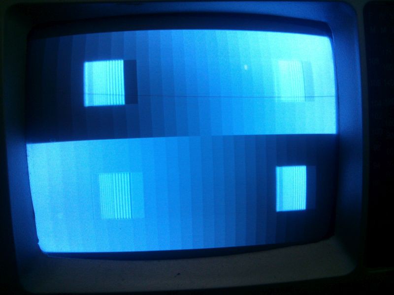
Some work has yet to be done to correct the color stripe right after the last vertical line. But I am happy for now.
Discussions
Become a Hackaday.io Member
Create an account to leave a comment. Already have an account? Log In.