 danjovic
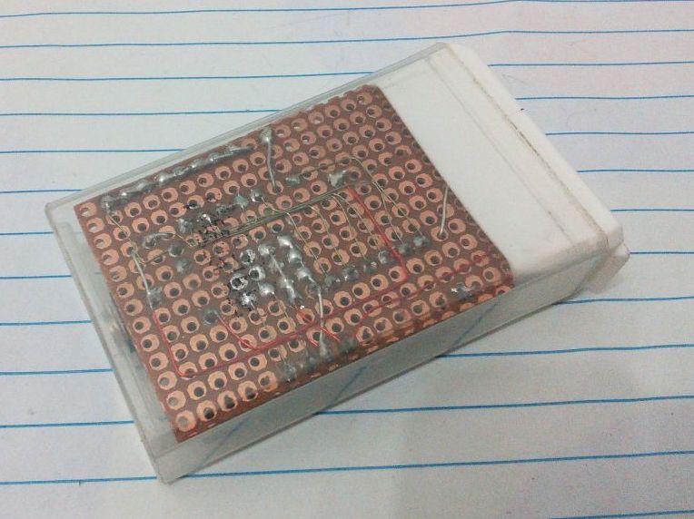
Finished assembling the prototype, but first fixed another issue that was a missing pull up resistor on RESET pin. Completely forgot about it because the first prototype, based on ATTiny85 had the RESET pin configured as IO thus such resistor was not required.
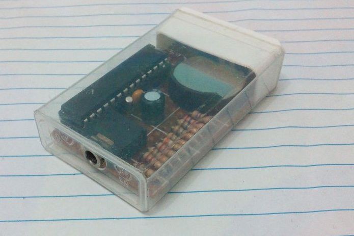
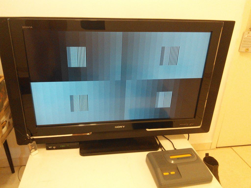
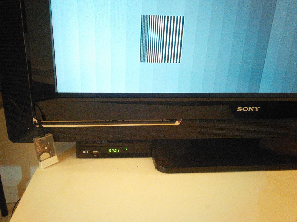
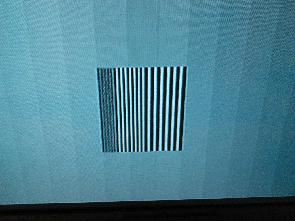
Noticed a couple of issues that might be, however, connected. First is the signal voltage that is 1.2Volts peak to peak with open circuit and 0.8 when terminated with 75 ohms resistor. The second issue is that the bars at the middle of the screen are somewhat scrambled again.
It will be necessary to perform a more acurate measurement of Voh and Vol on the circuit and this will probably influence the value of the resistors.
The resolution pattern was very clear on this TV set, as the thinnest line pairs could be distinguished. It demonstrates that this TV set analog circuits can deal with video content compatible with its native resolution (1360 pixels wide). Worth to remember that the test pattern is equivalent to a resolution of 850 pixels.
Discussions
Become a Hackaday.io Member
Create an account to leave a comment. Already have an account? Log In.