Emerica
-
Yay Progress.
01/03/2016 at 07:35 • 0 comments![]()
Hackaday Prize Done Twice over.
Ditching CC3000. Slimming down to basics for hamshack battery charging, will build up as needed.
Still want temp and light sensing/logging but not a priority.
Arduino mega
DFRobot Mega Sensor Shield 2.4
DfRobot Voltage dividers x2
DX 20A Current Sensors
Ebay 5A buck converter, with charging protection
Switching Psu
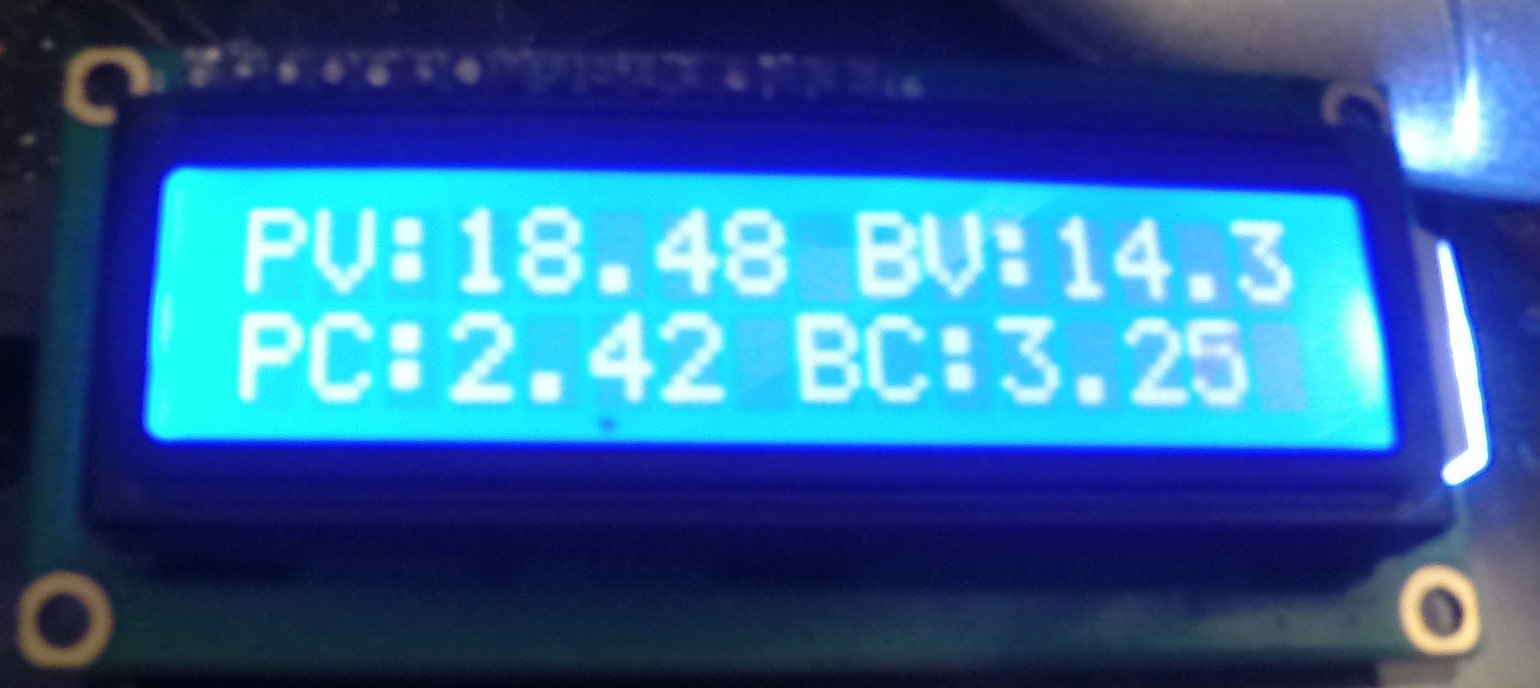
LCD
Debug/NormalSleep Switch
Might use RTC/SD Card for logging
Temp, Light, Relay etc all left aside for the moment.
2 modes selected by switch,
Mode 1, delay 1000ms, always on quick update for debugging during setup.
Mode 2. check sensors, delay 8000ms, kill backlight, then put arduino to sleep for 52s -
Spring is here.
04/08/2015 at 21:23 • 0 commentsI really should have been working on this over the winter, but Ham radio took over, between work, snow activities and HR, I was kinda swamped.
While doing some spring cleaning I found a voltage regulator I ordered last year in hopes of making the arduino run more efficient from the batteries. The vreg on the arduino itself is not very happy bringing ~13V down to 5V without making tons of heat.
This adjustable regulator DE-SWADJ seems to be working rather well, stays cool and so does the arduino.
I've set it about 6.3V, anything less and the LCD starts to become hard to read, with the onboard regulator.
I've now dropped it down to 5.5v and used the vin, any lower and agin the lcd becomes faded.![]()
Planning to order some voltage sensors to replace my dividers, and maybe a sensor shield to clean up a bunch of the wiring.
I've also found a bunch of proper stand-offs that I can set into the plastic sheet and mount everything better.
More progress as time allows. -
Didn't make the cut... Oh well , Space is a vacuum and vacuums suck.
08/25/2014 at 21:18 • 0 commentsWell, I've had SAM on the panels and connected to the web, off an on for the past couple days. Saturday I ran into reset problems. It seemed when the panel/battery voltage was brought over 13.5V the arduino and shield would reboot.
I got a regulator kit from our electronics shop lm317 I think? and it now sits in between the battery voltage and the arduino system, I have it set for 7V, but I might bump that to 9V ?
I'm having some problems now with the temperature sensors, so I bought new ones some replace the ones I mangled a bit. Temp sensing on the panels is broken at the moment, system temp is ok.
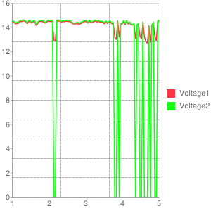
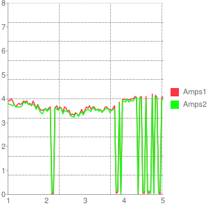
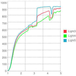
The charge controller is showing it's worth now. What seems to be happening is when the charge controller gets the batteries up to the 14.4V it shorts out the panels.
I loose sensing on the voltage and amperage. Sun still shines bright giving me nothing.![]()
![]()
![]()
-
Box progress, almost there.
08/18/2014 at 14:31 • 0 commentsSAM is coming along, much of the junction box is now mostly complete and I finally put the top cover on properly.
There is still work to do inside, mostly sealing the box and replacing the sma cable that I broke, which connects my external ant. You might see a laptop ant in the box right now, with it's long skinny white wire looped around inside.
I tried to keep the number of wires floating around inside to a minimum and am happier with less of a rats nest inside. Much of this was done by routing power and ground around on the backsides of the relay and power boards.
The power board Contains 2x 20A current sensors and 2x voltage dividers.
I left headers to the solar panel and the battery connections there and also bring the 5v from the arduino to a set of headers on this board.
I have a bunch of cat6 and had the keystone jacks laying around from another project, seeing as I used cat6 for the sun tracker and temp sensor wiring, it seemed fitting to use them and terminate the "module" ends with rj45 jacks. Not being any kind of electrical engineer, I'm not sure this is the right way to wire it all up, but values don't differ much, if at all, from the values of the sensors I had directly plugged into the arduino. I had it all on hand as well, so $ saved.
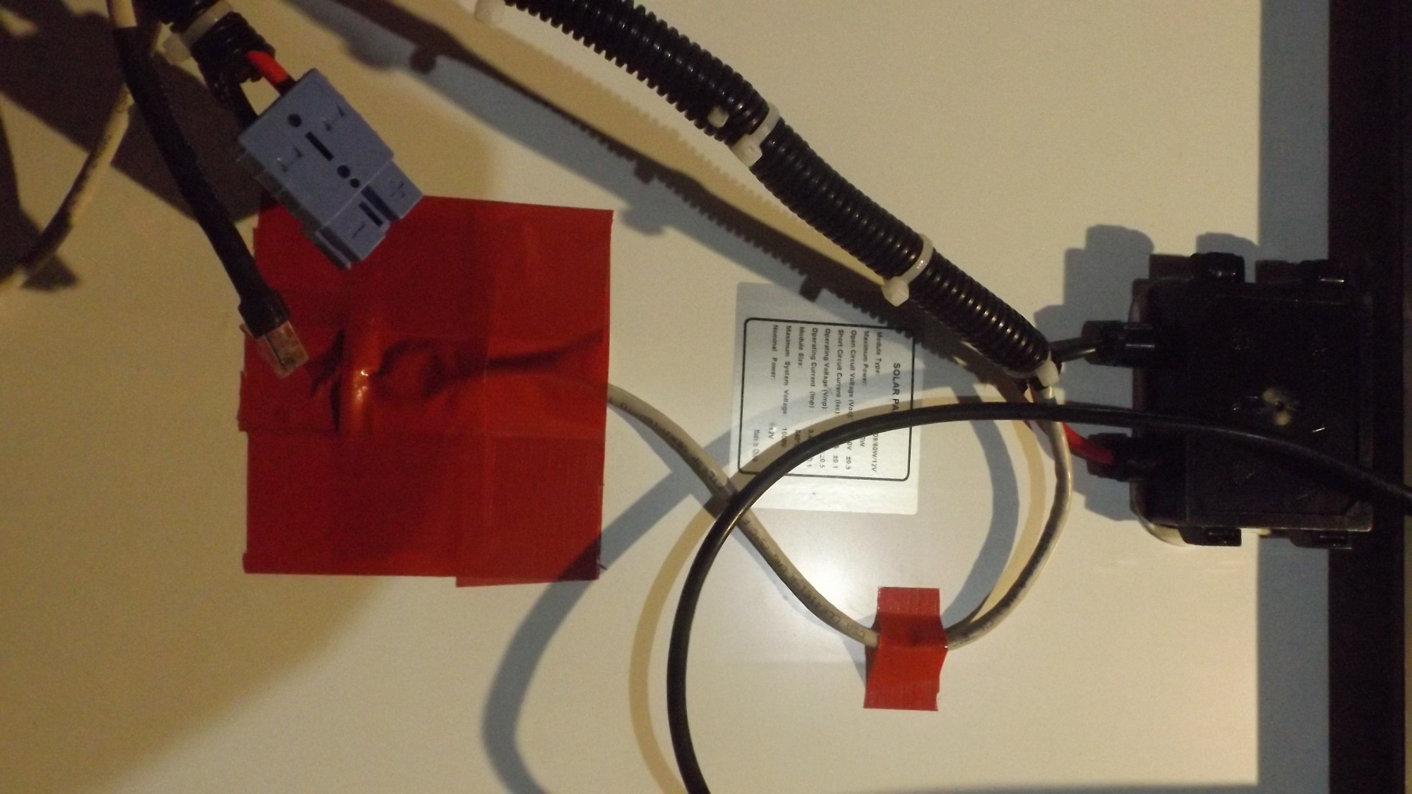
The temp sensors on the solar panels previously hot glued on, I thought it would work. I thought wrong. After the first day in 30C temps, the panels hit 55C and the hot glue fell right off on both panels.
I need to think about a better way to hold these on through summer and winter. For now I've duct taped everything to the back, I might have the same problem with it's adhesive. Time will tell and I can research alternatives in that time.![]() The small strip to hold it while I got the rest of the tape down.
The small strip to hold it while I got the rest of the tape down.
Basic todo list :
- build a bracket to mount the sun tracker to the top of the dish.
- mount the actuator to the dish so that it's able to rotate it without being in a stressed position
- Drill a usb and sd retrieval port. Make a cover with polymorph maybe?
- Get a new sma cable
- Seal the box
- Mount everything
- Program. -
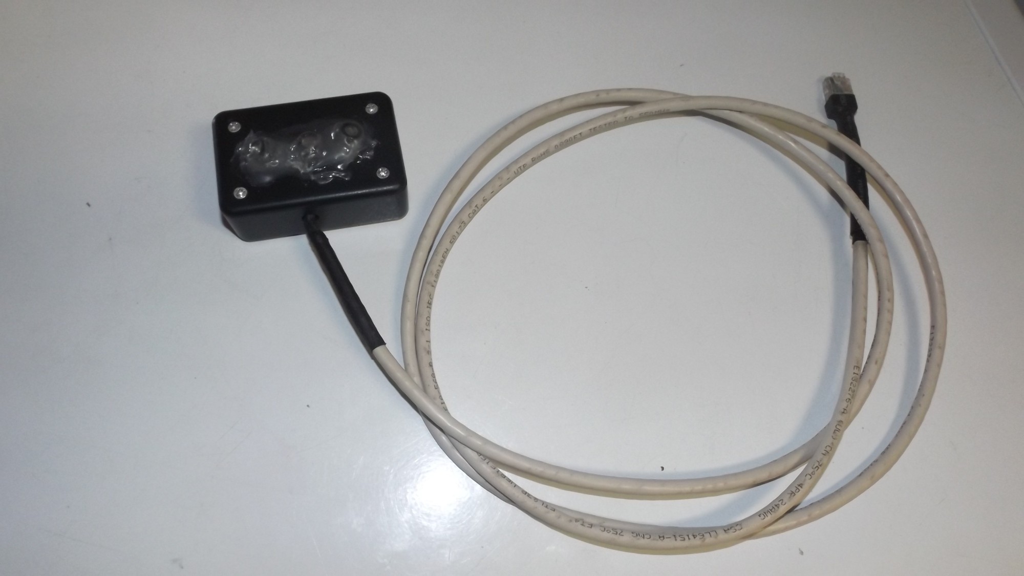
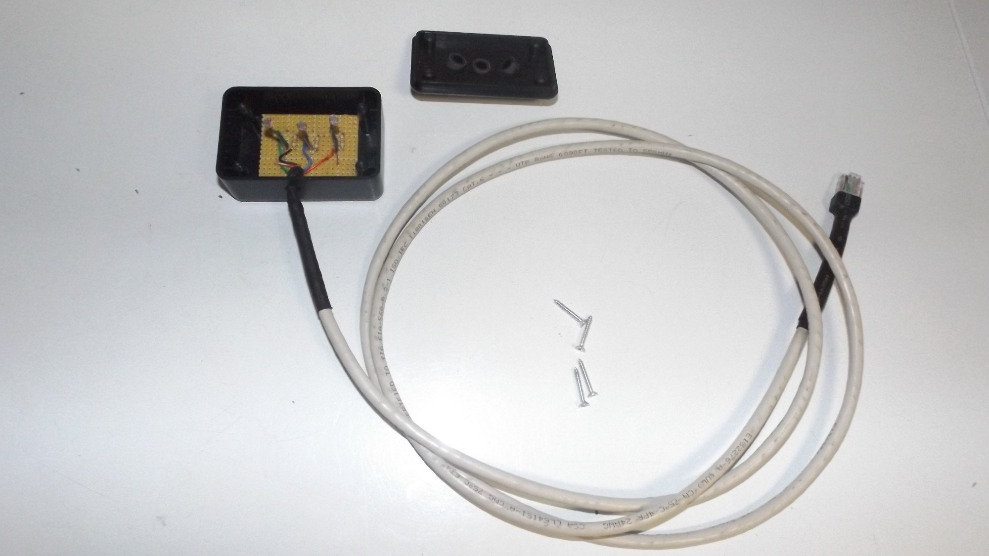
Sun Tracker Module
08/17/2014 at 05:09 • 0 commentsTesting the functionality of the sun tracker module
The suntracker is made from :
- a radio shack/ thesource project box.
- protoboard
- 3x photo resistors
- 3 resistors
- some cat cable,
- rj-45 jack
- heat shrink
- rubber tubing
- hotglueThe idea with this sensor is to try to always keep the middle sensor higher than the outside two. If you can do this , the sensor should stay pointed towards the brightest source of light in it's range, hopefully the sun.
![]()
![]()
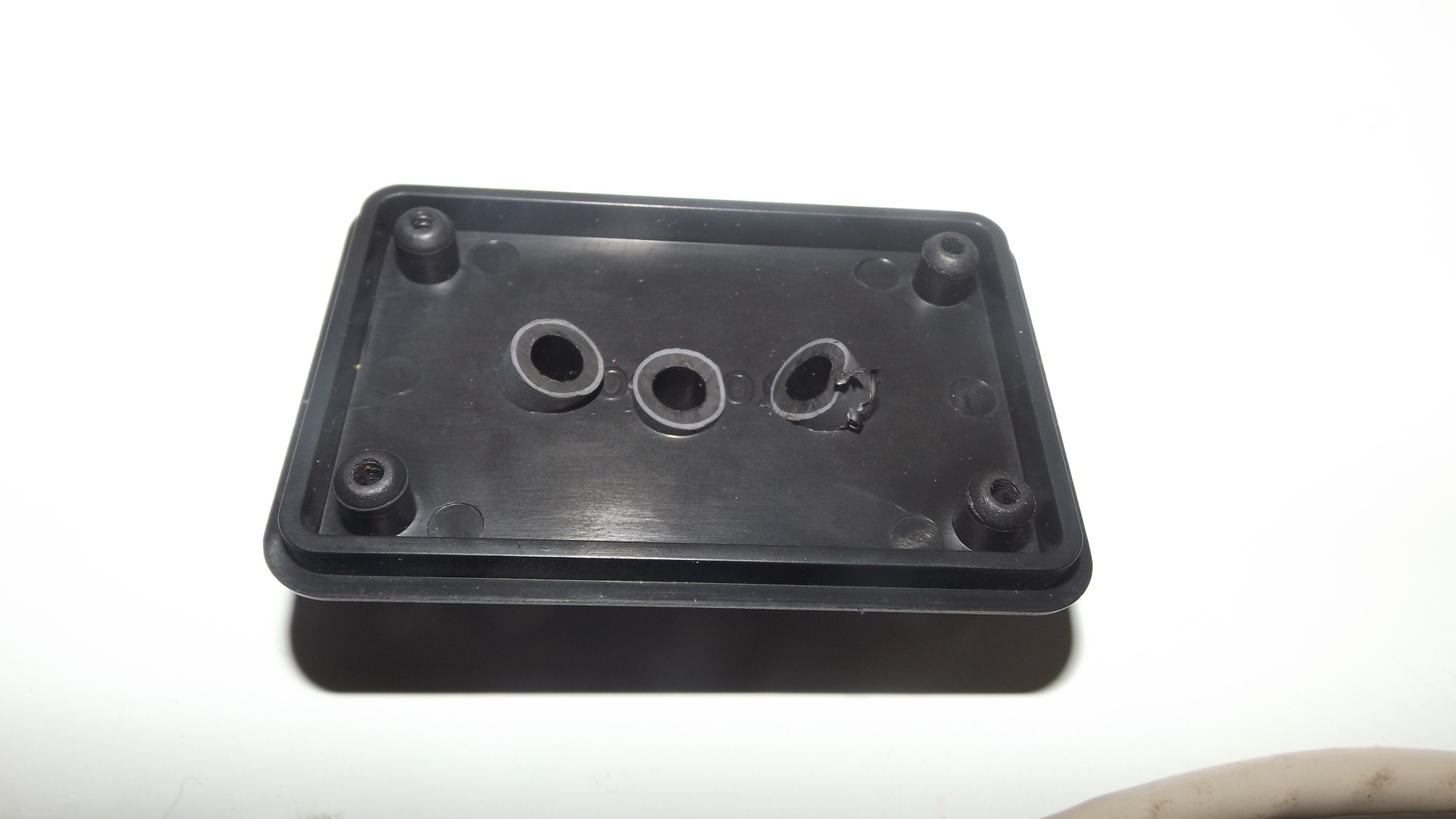
The two photo resitors on the outside are angled away from the center to be less sensitive to direct sunlight and to be more sensitive to side angles, like a sunrise or set.
![]()
![]()
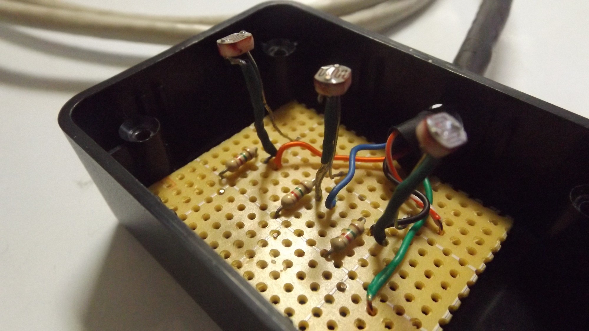
After trying a bunch of different photo resistors in the breadboard, I found that the sun was overpowering them and it was going to be kinda tough to have enough variance between sensors. I tried playing with different resistors, the solar garden lights with ldr's sometimes have a 15k omh resistor connected, so I tried 3 of those, or so I thought. 2 sensors maxed out in the sun and one was much lower, a reasonable reading I could work with.
Wondering what was going on I took a closer look at the board and noticed a red stripe instead of an orange one. 1.5K seems to work. So I changed them all to 1.5K. I'm sure this will vary with different photo-resistors so you will have to experiment, or dig into datasheets and do a bunch of math.
Hot glue holds in the tubes and diffuses the light, probably change over to silicone as the hot glue fell off the panels in the heat already.
I used cat6 to wire it all, rj45 for a connection to the box, I used heat shrink to help seal it up. The inlet and edges on the project box still needs to be sealed with some silicone. -
Actuator Control, New Battery, Desulfator
08/17/2014 at 05:08 • 0 commentsI got the actuator working, with the Arduino, not having a pot wire from the actuator, I wont have the position the actuator is at, There are limit switches so I will still be able to use it, just not as clean as I would like.
Found another deep cycle at the garbage running on a new pulser,seems like it's going to hold a decent charge.
I have since added this battery to the array, there are now 12 batteries in the array and the pulsetech pulser has been connected on all three since the video. -
More updates to the external enclosure.
08/17/2014 at 05:07 • 0 commentsStill more to go but here is another update on the progress of the junction box.
-
Relays are too much fun
08/17/2014 at 05:06 • 0 commentsI got the relay board working, very happy.
-
Progress on the Outdoor enclosure.
08/17/2014 at 05:05 • 0 commentsToying around with getting everything to fit in the box, found some wire from an also satellite receiver to connect the relay board. Just a bunch of tired rambling in this one, but it's coming together.
-
Moving off the breadboard to an enclosure.
08/17/2014 at 05:04 • 0 commentsI need a nice box to hold everthing, it needs to seal well, but it would also be nice to be able to see inside.
SAM - Solar Automation Machine.
Sun Tracking, Charging, Cooling , Monitoring, Relay control. for my small solar panel installation.

 The small strip to hold it while I got the rest of the tape down.