It starts with a model I found on Thingiverse. A cool case for an HC-SR501 motion sensor. (https://www.thingiverse.com/thing:3170870)
Since I had one of these lying around I wanted to add it to my smart home System.
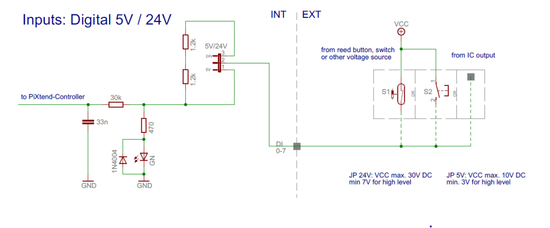
The nearest I/Os to the preferred location are the digital inputs on the Pixtend Extension Board.
The only problem is that the HC-SR501 sensor outputs a 3.3V Signal and the DIs need at least 3.3V to flip high.

(https://www.pixtend.de/files/manuals/pixtend_technisches_datenblatt.pdf)
My solution should only involve components I had already in stock. So I decided to use a BC547 NPN transistor.

The signal gets inverted but that's no problem since I can negate the input in the PLC. I also mounted a lux meter (a photoresistor board with 0...2.5V output) in the motion sensor case. The boolean signal of the motion sensor and the analog value of the lux meter are processed from the PLC and the light gets switched on when needed.
 stefan.schnitzer
Discussions
Become a Hackaday.io Member
Create an account to leave a comment. Already have an account? Log In.