Shervin Emami
-
Choice of Infrared Emitter LED
10/01/2016 at 04:47 • 0 commentsInfrared Emitter Options with 940nm wavelength (sorted by price):
Device: Peak Current: Radiant Power @ 20mA Beam-Angle: Shape: Price (single quantities): Multicomp OFL-3102 200mA 14mW 30 deg 3mm USD$0.16 Vishay TSAL5100 1000mA 5mW 10 deg 5mm USD$0.60 Vishay TSAL6100 1000mA 8mW 20 deg 5mm USD$0.61 As shown in my "Choice of Infrared Wavelength" section, sunlight has very little 940nm radiation, so my preference is to use 940nm. To reach long distance, I want high peak current and radiant power, and a narrow beam angle is likely to help too. Due to the high peak current of Vishay TSAL5100 & TSAL6100 and their narrow beam angles, it would be my ideal choice if I was using a constant-current source that could safely drive near the peak current. But the Multicomp OFL-3102 is a lot cheaper and still looks quite decent, the only problem is that the OFL-3102 datasheet doesn't give much graphs of its behavior. I'm guessing it's capable of 500mA or similar peak current when driven by a pulse at 0.01 duty cycle for just a few microseconds, even if it's not shown in the datasheet. And it seems to have more radiant power at low currents compared to TSAL5100, and is slightly smaller. So I will try using the Multicomp OFL-3102 emitter LED, since it seems to be more efficient at 20-50mA that I'm expecting to drive it with, and the cost savings would be noticeable to someone in the 3rd world that might want this on 4 fingers with 4 LEDs. If I eventually find that the OFL-3102 with a current-limiting resistor doesn't give enough distance range or reliability, I might eventually switch to using a constant-current power source with the Vishay TSAL5100 LED in the future to get long-range measurements.
-
Controlling the Infrared emitter LED
09/30/2016 at 13:28 • 0 commentsAll LEDs (including Infrared Emitter LEDs) produce light based on the amounts of current flowing through the LED. So to get the furthest range from an IR emitter LED, I want to put as much current through the LED as reasonably possible. If I put too much current through the LED, it will either die instantly or get hot very quickly and then die from overheating. And there's also the problem that LEDs have a very sharp voltage vs current curve, where feeding an LED just 10% more voltage than recommended will cause a significant increase in current, often killing the LED. That's part of the reason why instead of simply using a (current-limiting) resistor in series with the LED, high power LEDs are nearly always driven using a "constant-current" power source, to make sure the current stays fixed even if the voltage or battery level varies. Some examples of simple constant-current LED driver circuits are:
- Using a Transistor + 2 Diodes : "https://www.analysir.com/blog/2013/11/22/constant-current-infrared-led-circuit/"
- Using a MOSFET + a Transistor: "http://www.instructables.com/id/Power-LED-s---simplest-light-with-constant-current/step2/Specs-Function/"
- Using a MOSFET + a Voltage Regulator: "http://www.instructables.com/id/Super-simple-high-power-LED-driver/step2/How-it-works/"
For this project, it might turn out that I will need to use a constant-current power source. But I'm going to try to get by with just a current-limiting resistor. (Note that a "current-limiting" resistor is just a normal resistor). And if I'm not using a constant-current power source, I should probably at least use a voltage regulator so I have a constant-voltage power source for that resistor, but I'm going to try to get by without a voltage regulator as well! A constant-current power source has the advantage of giving good control of the current to the LED for safety, as well as being more efficient than simply using a resistor. But by powering the LED just for very short bursts, and not pushing the LED quite to its limits (since I'm not aiming for the absolute longest range possible from the LED), I'm hoping the LED might be used near its limits but won't blow and also it shouldn't be too inefficient since the LED would be off most of the time.
This means I need to be very sure I don't power the LED long enough for it to overheat, and make sure I stay within absolute ratings so it doesn't instantly blow the LED even when the battery is slightly overcharged. According to "http://electronics.stackexchange.com/questions/55823/how-can-i-efficiently-drive-an-led", when simply using a current-limiting resistor I should put atleast 25% of the voltage through the resistor to ensure there is enough voltage difference for the LED to operate in. Assuming the device is powered directly from a single-cell rechargeable LiPo battery, the battery voltage would be between 3.3V when flat to 4.2V when fully charged. LEDs are nearly always less than 2.0 V, so this means there is enough voltage gap for the current-limiting resistor to cover atleast 25% of the voltage when in series with the LED.
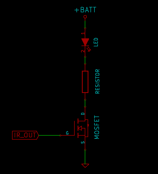
So the LED driver circuit I'll use is as simple as:
![Very simple LED driver circuit]()
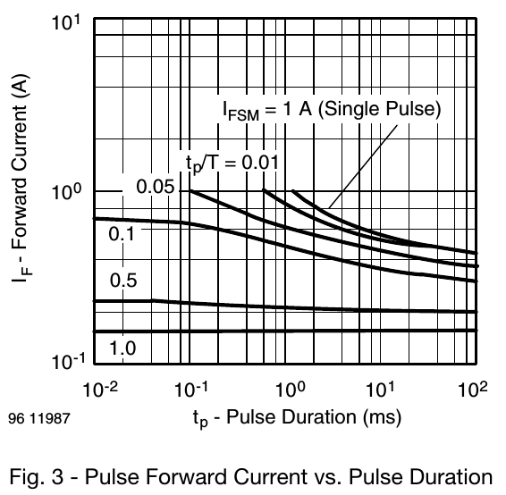
Note that using such a simple LED driver while still trying to reach roughly 50% of the absolute max rated current means I need to be sure the microcontroller only leaves the LED on for very short durations, and leaves it off for majority of the time. The datasheet figure below shows the effect of pulse length and duty cycle for the Vishal TSAL6100 Infrared emitter LED, showing that the LED can handle several times more current if it's a very rare pulse (eg: tp/T = 0.01) compared to something like a pulse with 0.5 duty cycle (ie: switched on half the time and off half the time).
![Effect of pulse length and duty cycle for Vishal TSAL6100 Infrared LED]()
Looking at the datasheets for 2 IR emitter LED's I've been considering (Vishay TSAL6100 and Multicomp OFL-3102), it seems I should power the LED for under 0.1 milliseconds at a time, and use less than 10% duty cycle. If I use 0.1 ms pulses and want to measure around 100 times per second (so the behavior of the device feels smooth), that means the LED would be on for roughly 10ms per 1 second, or a duty cycle of 1%, fitting well within my limits and keeping the battery draw quite low. There are other factors that will effect the timing besides the LED emitter time, such as the time it takes the ADC to measure the analog signal. By default, a 16MHz Arduino needs 13 cycles of the 125kHz ADC clock to measure an analog voltage, so roughly 0.1 ms. Adding the roughly 0.1 ms for the clock pulse with the roughly 0.1 ms for the ADC reading means we are still talking about a duty cycle of just 2%.
Something I've been wondering about is how long the LED pulse should be. I know the ADC needs roughly 0.1ms per measurement, but I'm not sure how long it would take for the IR LED to generate light and the light to bounce off the object and the IR photodetector to fully adjust to the signal. Maybe they all happen in a few nano-seconds, but maybe the LED needs hundreds of micro-seconds to warm up and reach its full brightness, and maybe the photodetector needs hundreds of micro-seconds to ramp up to the full value. If so, the reading by the microcontroller might need to be delayed in order to make sure the signal is at its strongest.
So I will borrow my friend's Oscilloscope, to measure just how long it takes the IR photodetector to reach its peak output after an IR pulse has been emitted.
-
Method of distance detection
09/30/2016 at 11:34 • 0 commentsThere are several different ways you can measure distance to an object using IR:
- Reflected light intensity: The easiest method is to send a beam of IR light and then measure how much IR light has reflected off the object. It only needs an IR emitter LED and an IR receiver. Think of it like pointing your TV remote at your ceiling and the signal gets reflected into your TV. The IR receiver will generally receive more IR light when the object is closer to it than when the object is far away, so this can be used as a simple way to measure distance. It's not perfect, some surfaces will reflect more light than others, such as shiny white objects compared to matte black objects, but it can be good enough for some purposes. This has traditionally been done using sensors by Sharp such as the GP2Y0A21YK at Sparkfun for $14, but they're somewhat expensive & large for a DIY finger-worn device affordable in the 3rd world. Luckily a custom sensor could potentially be much cheaper & smaller and with much faster response than the Sharp sensors.
- Projected light: To measure the distance to many points on an object at the same time, we can project narrow strips of IR light and see how the reflection is deformed from a nearby camera. This is the method used by some consumer motion tracking devices such as the Xbox Kinect and Intel RealSense, but is too complex & expensive for a DIY finger-worn device.
- Time Of Flight / LIDAR: We can send out a pulse of IR and measure the amount of time between sending the pulse & receiving it. Since we know the speed of light, we can calculate "distance = speed x time". This method is significantly more reliable & accurate & consistent, but unfortunately the equipment has been fairly large & expensive, such as the roughly $100,000 2D LIDAR sensor used on Google's self-driving car or the $150 LIDAR-Lite.
Comparing the 3 options above, a simple custom-made reflected light intensity sensor still seems like the best option for this project, since it should be small & cheap enough to have 2 or 3 of them on a person's hand and with almost-instant response, making it great for instant feedback, compared to the more complex devices mentioned above that only update around 30 times per second.
-
Motivation for the project
09/18/2016 at 11:10 • 0 commentsAs a very "hands-on" Robotics Engineer, I've worked on many highly complex state-of-the-art robotics & computer vision systems around the world, from self-balancing robots that can climb stairs, to humanoid robots that can talk & recognize faces, to writing some of the fastest graphics and image processing software in the world. But after working on a robot for the US military, where I eventually realised the robot I was having fun building was actually intended to potentially kill women & children one day, it really changed my view on what projects I want to work on. I felt like one of those scientists who first designed the atomic bomb just for the sake of science, but as they say, with great power comes great responsibility. So in recent years I've been looking for ways to eventually put my skills & experience towards helping nature or people in need.
Luckily many of the technologies useful to robots are also useful to humans with disabilities. My main interest in robotics has always been in "robotic vision", ie: giving sight to a mobile robot. Similar techniques can also be used to give sight to a blind person! So I want to make a wearable device for blind people that helps them detect the distance to nearby objects. Many blind people use a walking stick to sense distances while walking, but a walking stick isn't too practical for sensing shorter distances such as sensing the items in front of you. So my device is not intended to replace a walking stick, it's intended to complement a walking stick and other tools, such as to help a blind person find objects on a table or cabinets in a kitchen, or find the toilet seat without having to touching it.
Being a Robotics Engineer, my initial designs were similar to how various well-funded university labs had tackled this problem: highly complex systems that need powerful computers to process 3D data from stereo cameras worn on the head, resulting in devices that cost around $10,000 just in parts.
But after living for a while in the 3rd world, and finding out that according to the International Agency for the Prevention of Blindness, 90% of the world’s 39 million blind people live in developing countries. So my main goal was to make the device useful but still affordable in the 3rd world. This required a radical change in how I tried to design the product. Instead of starting with a highly complex product and hoping it can eventually become affordable, I decided to tackle the problem from the other way: build the simplest, cheapest blind assistance device I could invent that would still be useful, and then worry about adding extra features later!
With my roughly 20 years experience in robotics, I knew there were far simpler solutions for measuring distance to objects than using 3D camera systems, such as Ultrasound, Infrared, Radar, or LIDAR. In fact all of these sensors are commonly used on robots, so I already knew the strengths and weaknesses of them all. Radar and LIDAR are highly reliable, but usually very large and expensive. Ultrasound is cheap and fairly small, but is extremely unreliable. Every time I tried to use Ultrasonic sonars for robots or other projects, they have always proven to be quite useless, especially on robots that are moving around in the real world. Quite often, even the expensive types of Ultrasonic sensors aren't reliable enough to detect someone's feet in front of a robot at times. So that leaves Infrared as the sensor of my choice! I've seen several other projects on Hackaday and elsewhere that try to measure distance to objects for the blind, but they have all been based on Ultrasonic sensors, such as Pathfinder, but as mentioned above, I'll be making one that sense distances based on Infrared.
Once the device knows the distance to the object, it can inform the user by vibrating their finger. For the initial device, it would simply vibrate more as the object is closer, but some people might prefer that the vibrations stay the same strength but change in frequency as the object gets closer.
DepthIR: Object detection for the blind
A wearable device for blind people to measure distances to objects without touching them