Close
0%
0%

Soft-Handy

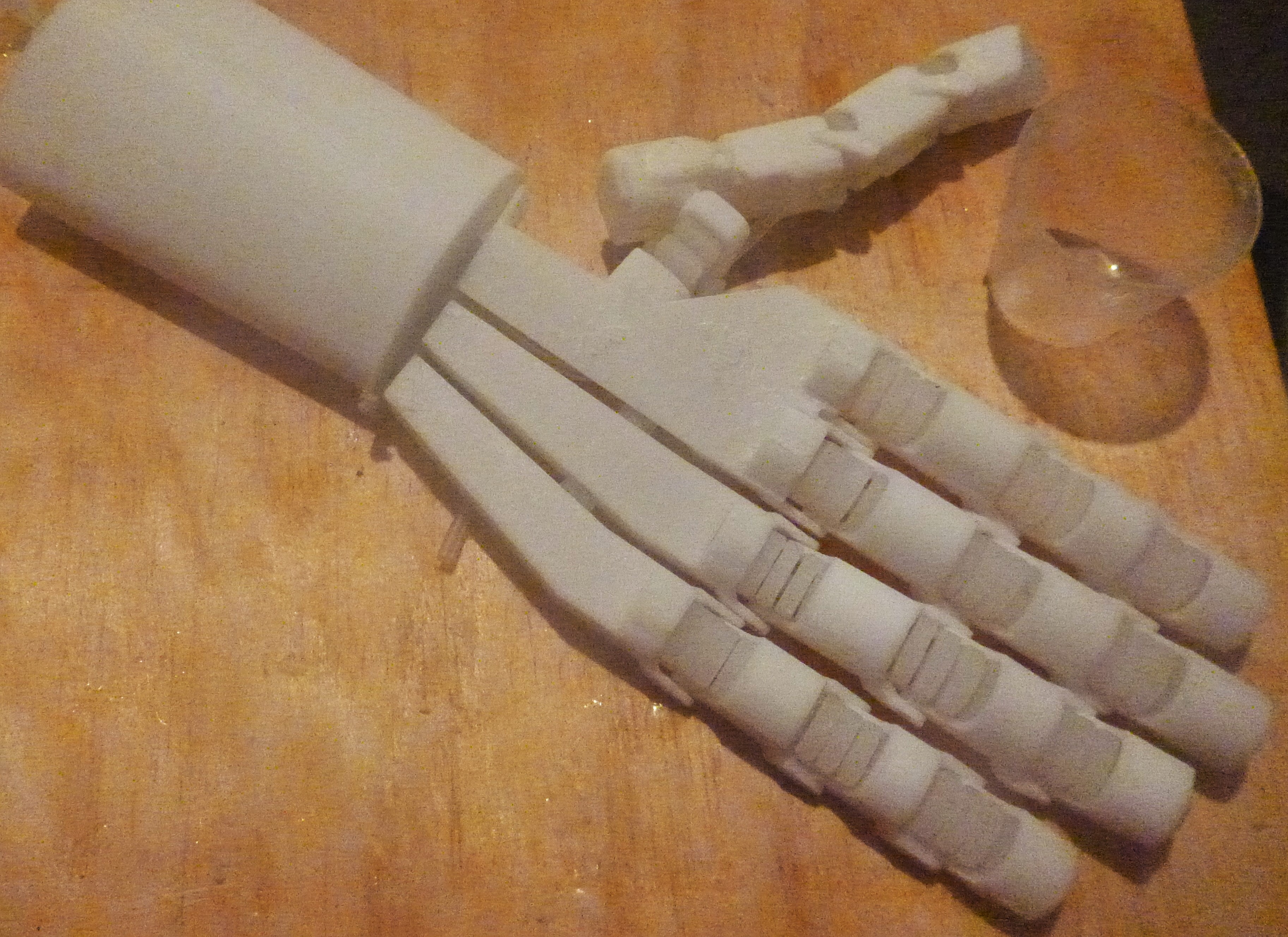
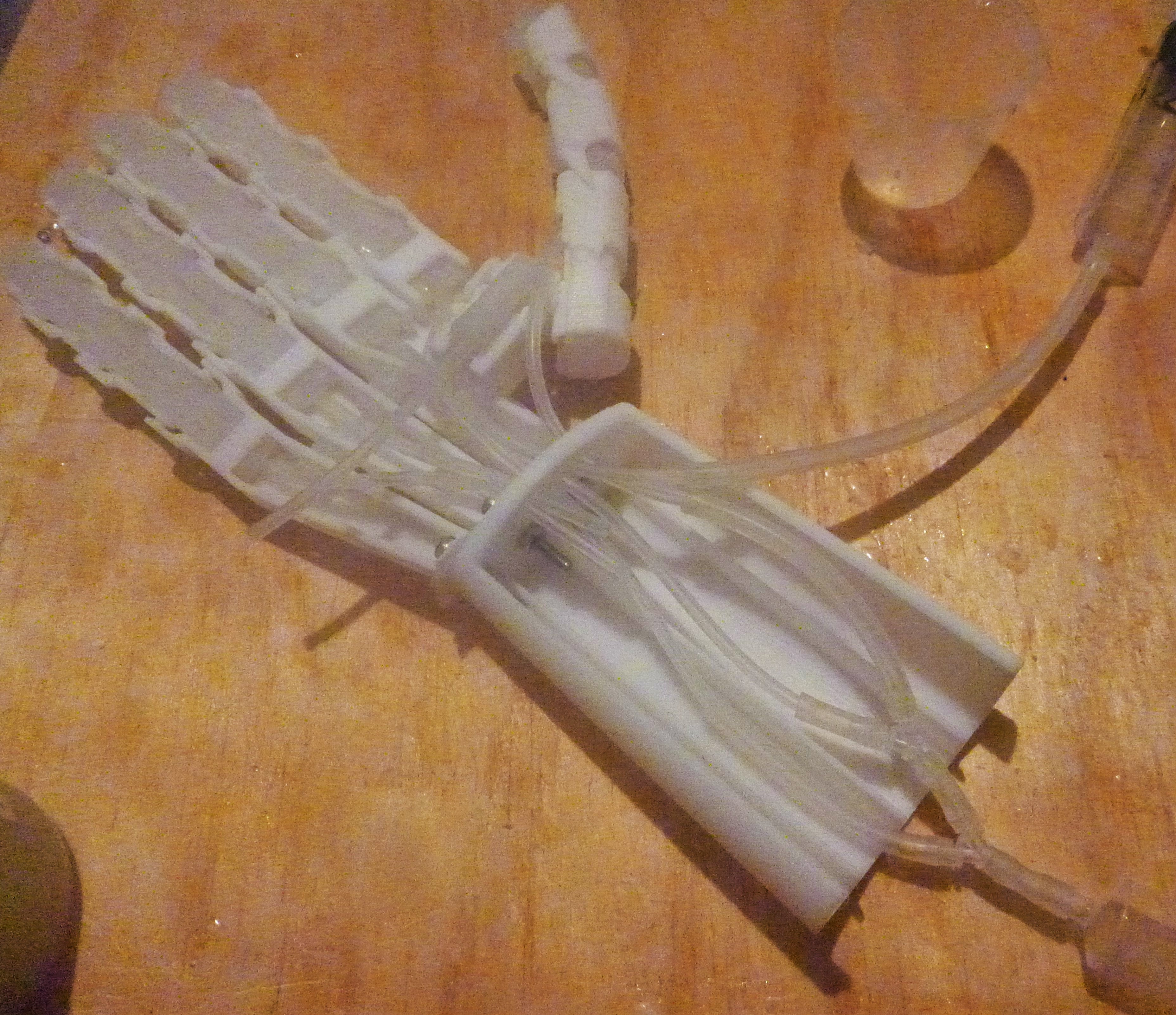
This project is an exploration of a pneumatic artificial hand that could be used for a robot or as a prosthesis.

Similar projects worth following
Among the large number of robotic and prosthetic hands that have been built this another. The idea with this one particular is that it is pneumatically actuated that applies principles of soft and social robotics. There numerous reasons why a pneumatically actuated hand would be beneficial as the pressure equalizes through the system. For a hand this should enable the grip to be constant and strength controlled with the pressure.

Social robotics states that a robot has design orientated towards the human environment. Including this principle is natural for this project if it is orientated towards prosthesis. Importantly for a prosthetic hand is that it resembles in look and function a human hand with all the socially interactive behavior.

The majority of the hands hardware of this project is 3D printed abs with the soft actuators made with silicone. Soft robotics is used to mimic biological behavior combined with a skeleton makes a similarly functional appendage.

The aim of this project is to create a prosthetic hand that would be more appealing to a teenager as opposed to the many opensource hands available to the under 12's. Thus the difference is mostly aesthetic in form and function, that is more relational and nuanced.

For a prosthetic hand to aid function and a humanoid robot to function as you would expect it to the artificial hand must not only be similarly functional but have an appearance of handness. Hands that function as social objects as much as environmental manipulators. Gesturing, high-fiving and handshaking require handiness to perform such communicative roles. So it is with this emphasis that as well as a environmental manipulator this project aims to create a more sociable hand.

Softness is an important property of this hand, so soft robotics is clearly and inspiration with the mechanical functions being a direct response.

Link to the CAD models:

https://grabcad.com/library/soft-hand-1

Composition

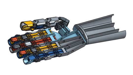
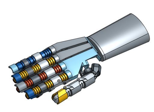
The hand comprises of a hard ABS 3D printed exoskeleton is a soft silicone core for control and actuation. Having a hard exoskeleton limits the degrees of freedom for the appendages much like an insect. Softness is essential if an object is to interact with a noisy environment with unpredictable angles and surfaces allowing compliance.

It will also have a control electronic with a pump, valves and sensors to give the hand a user friendliness. One each air line there will be a air pressure sensor and a solenoid inlet and outlet valve to regulate each fingers actuation and limit the amount of pressure.

hand_actuation_v1.ino

Initial Control software

ino - 4.98 kB - 10/05/2016 at 12:38

Download

  • 1 × 1mm silicone tube
  • 1 × 2mm silicone tube
  • 1 × y-type connectors, 2mm
  • 1 × 0.5mm Shore 50A silicone sheet
  • 1 × Shore 10A two part silicone Depending upon your region different brands are available.

View all 12 components

  • Control electronics_1

    Nelson Phillips10/09/2016 at 04:25 0 comments

    After morning the loss of my CNC spindle........ and a bunch of side tracks this project continues.

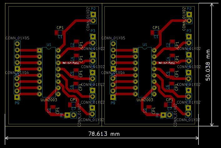
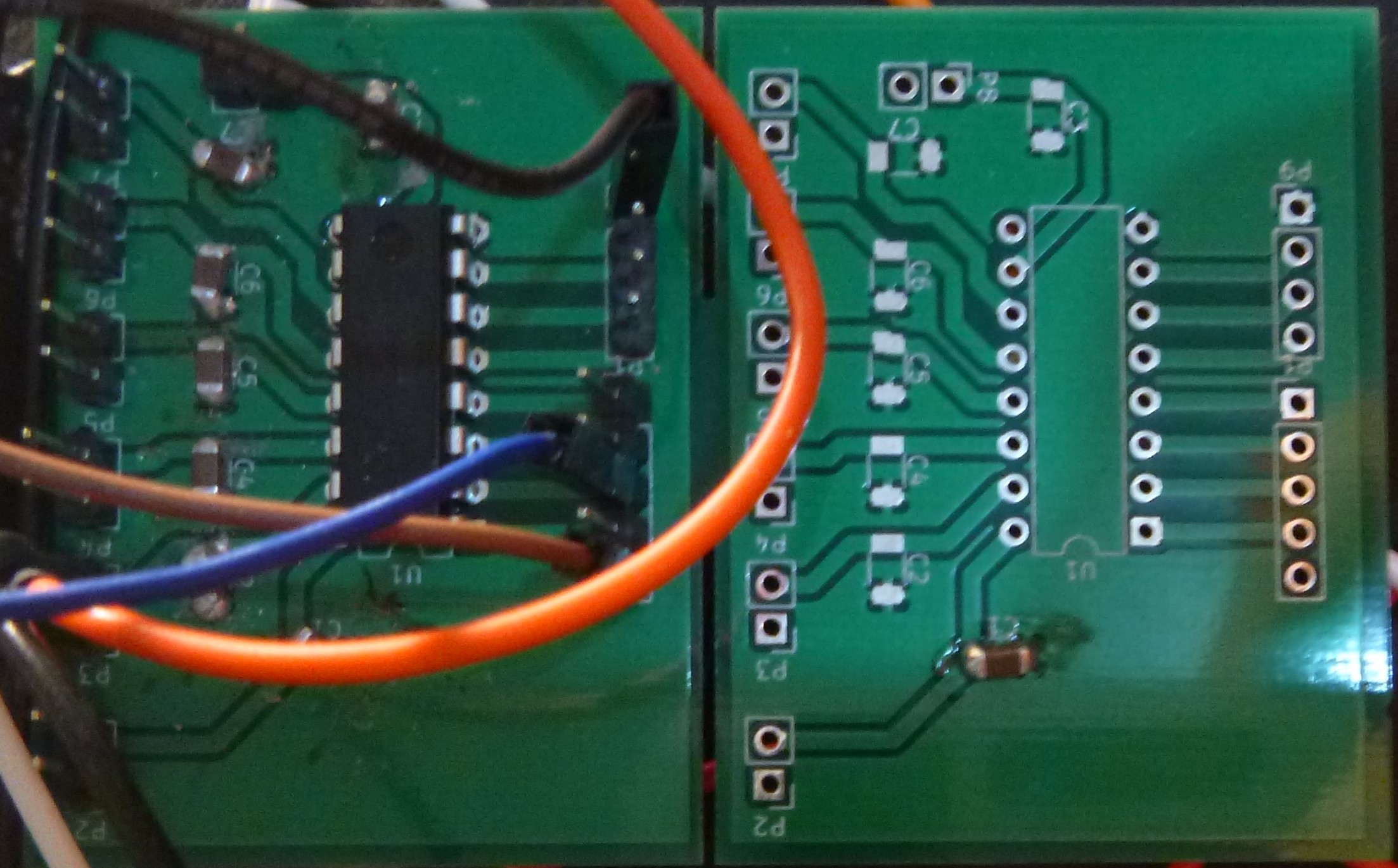
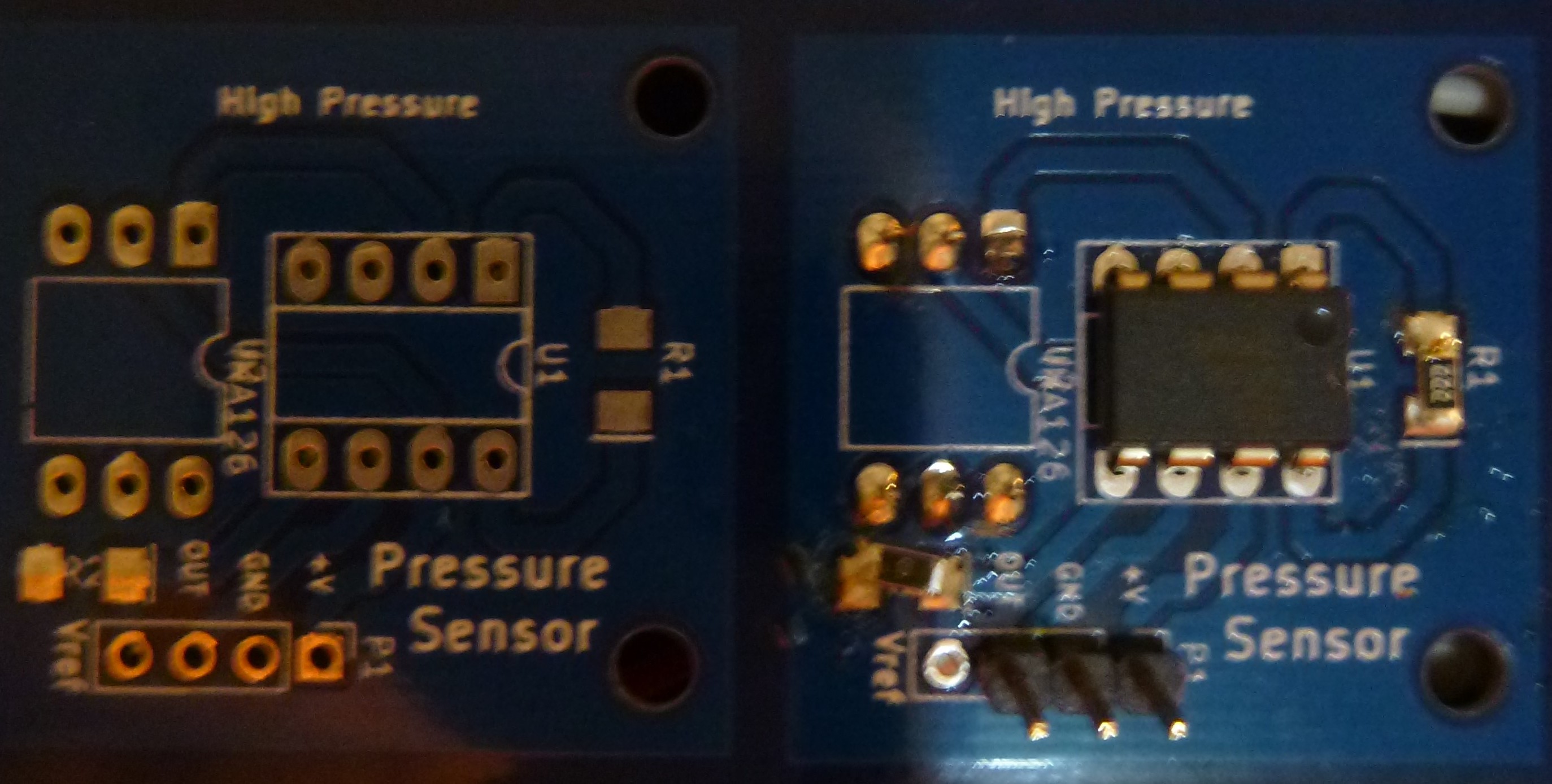
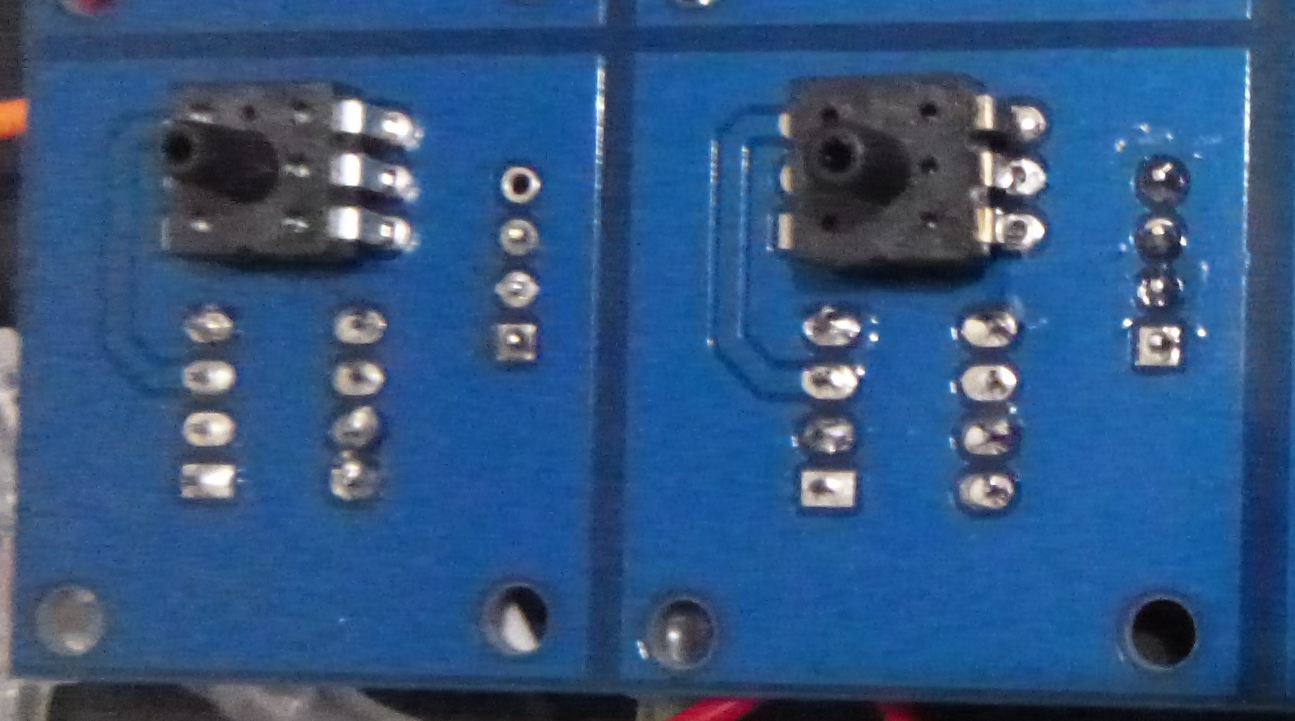
    The control circuit for the pneumatic actuation requires a air pressure sensor and a valve driver. Both the pressure sensor and valve driver was designed as separate pcb. 

    The outline of the pneumatic circuit uses the following outline. A solenoid valve releases the pressure into the pneumatic circuit with the actuation of individual fingers via another solenoid valve in series. In this way any actuation powers the inlet valve and fingers valve. The intention is to enable the pressure to controlled either by a variable valve or second pressure vessel.

    Valve driver.

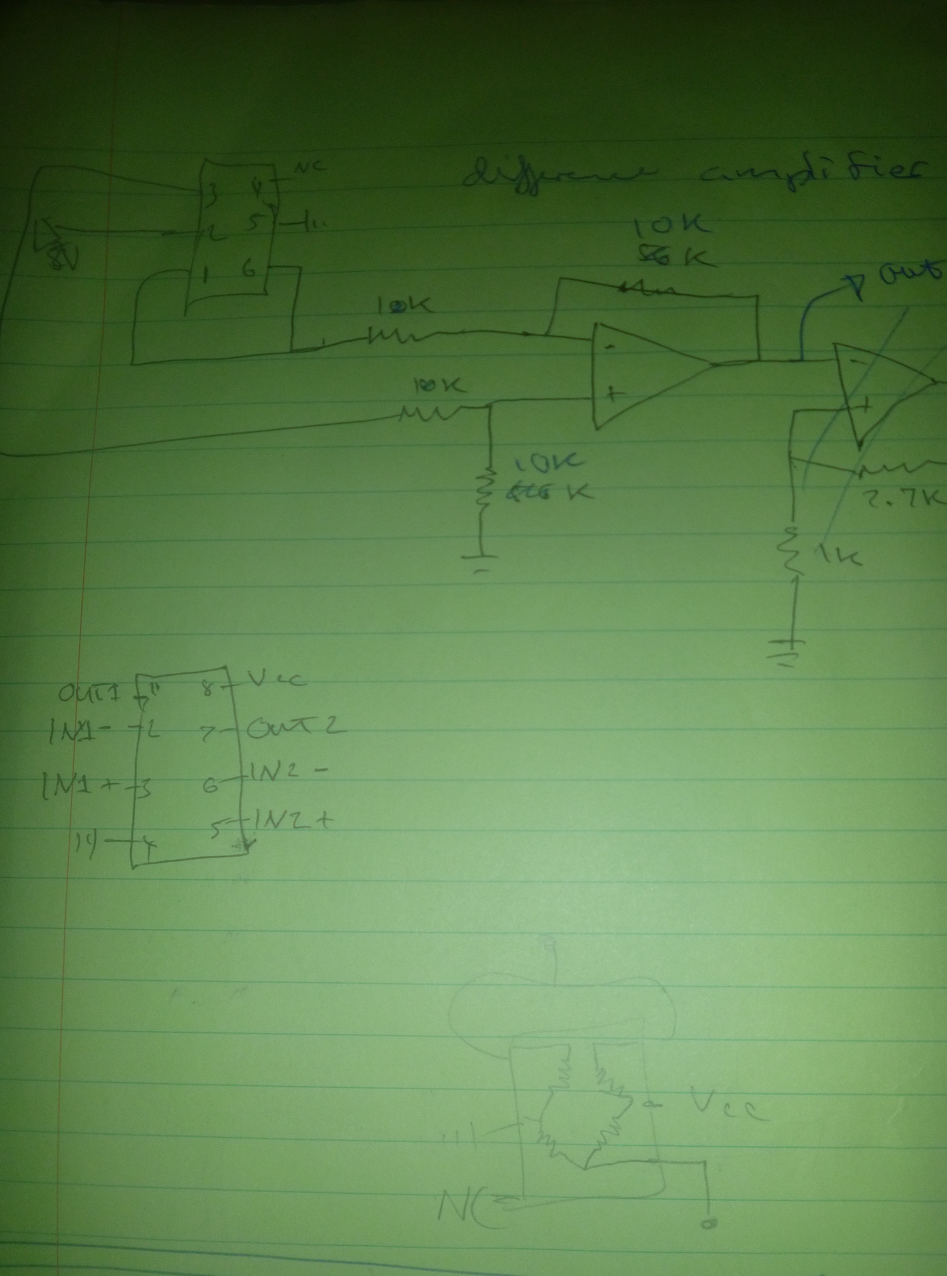
    Pressure sensor uses a Wheatstone bridge sensor, instrumentation amplifier and gain resistor. 

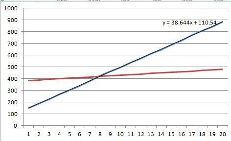
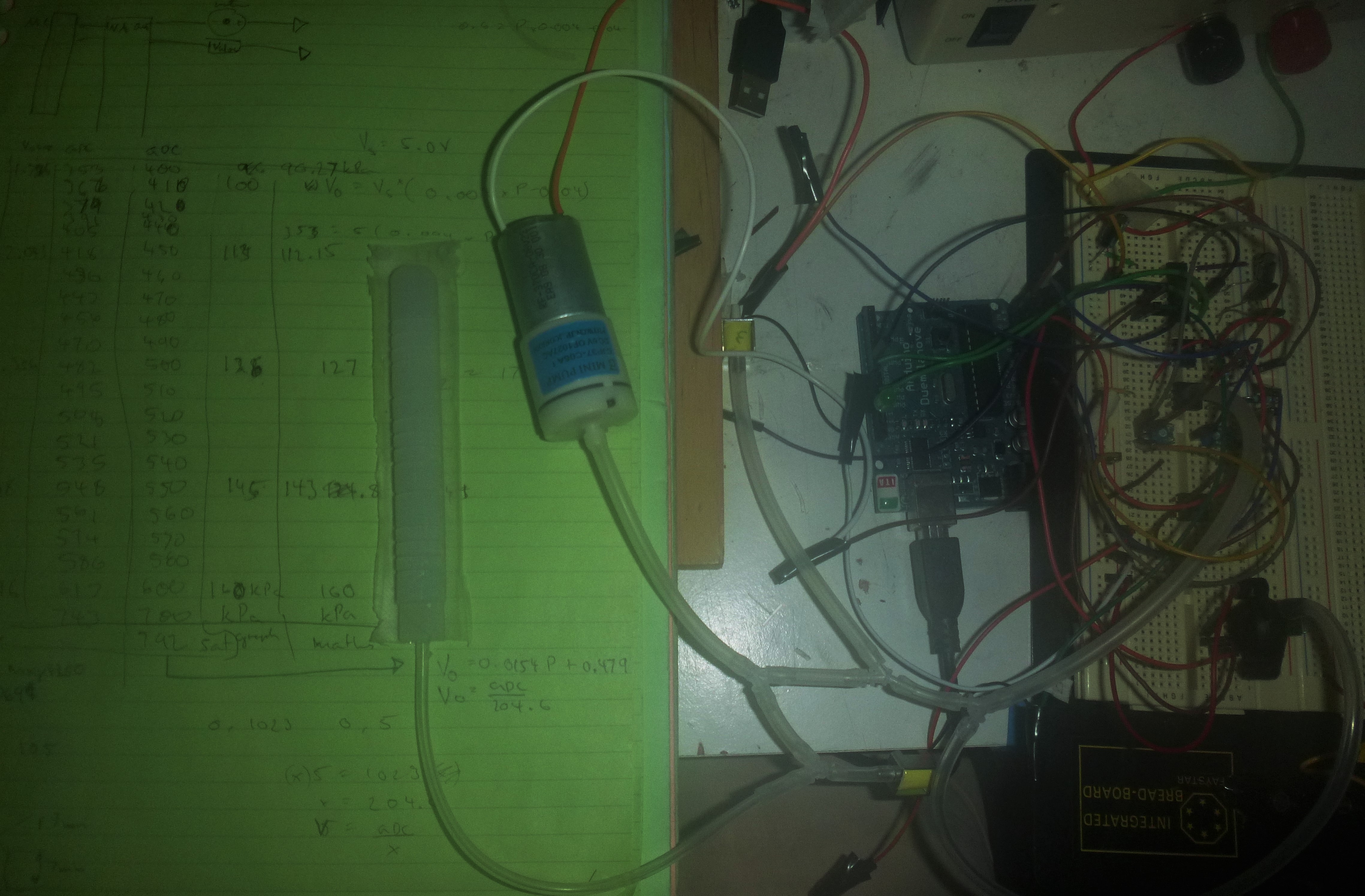
    Coordinating the control of the pneumatic circuit used a MPX4250 to calibrate and select the gain resistor. The method used was to link the sensors and write the analogue values through 20 increment by 5 relative to the MPX4250. This also gives a linear equation for future reference.

  • Control electronics_1 - schematic

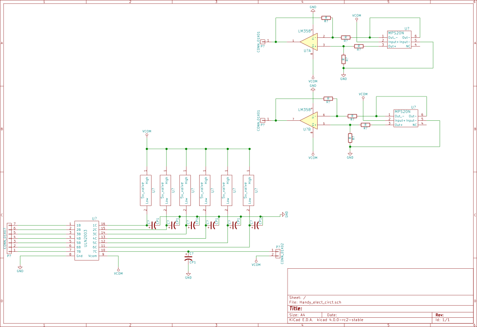
    Nelson Phillips10/07/2016 at 07:06 0 comments

    The control electronics schematic for the motor, valves and pressure sensor.

  • Control electronics_1

    Nelson Phillips10/05/2016 at 12:42 0 comments

    The initial software and hardware for the control of the hand has been done. It basically doesn't blow the fingers up. A calibration test was done to understand the readings of the sensor to activate a comfortable amount of pressure in the actuators. Then a basic control sketch was written and tested with the intention of this to be the basis for a more complex control regime.


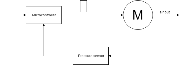
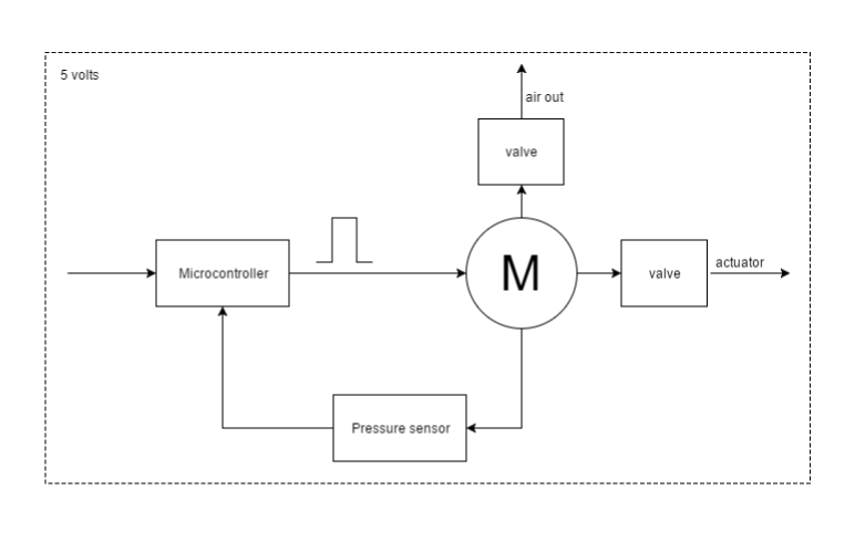
    The function diagram represents the components with the valve in open loop and the sensor in closed loop. Using pwm to control the motor pump will enable the feedback sensor to proportionally change the output of the motor. There probably not a necessity to implement a full PID control and currently just the P will do, but the possibility is there for the future.

    The whole system runs off a 5 volt power supply, as shown in the video this is definitely enough and will probably need to be carefully regulated so as to not blow a finger.

  • Grasping

    Nelson Phillips10/03/2016 at 07:35 0 comments

    Just a short log with a video of the hand grasping at a suncream container. It doesn't pick the container up, with my thinking if a put the finger pads on it have instead of the ABS exoskeleton just slipping over the surface.

    Playing around with what this hand can pickup and especially because it is a soft hand it should be capable of grasping different/oddly shaped objects.


  • Beginning of the control electronics

    Nelson Phillips10/02/2016 at 11:47 0 comments

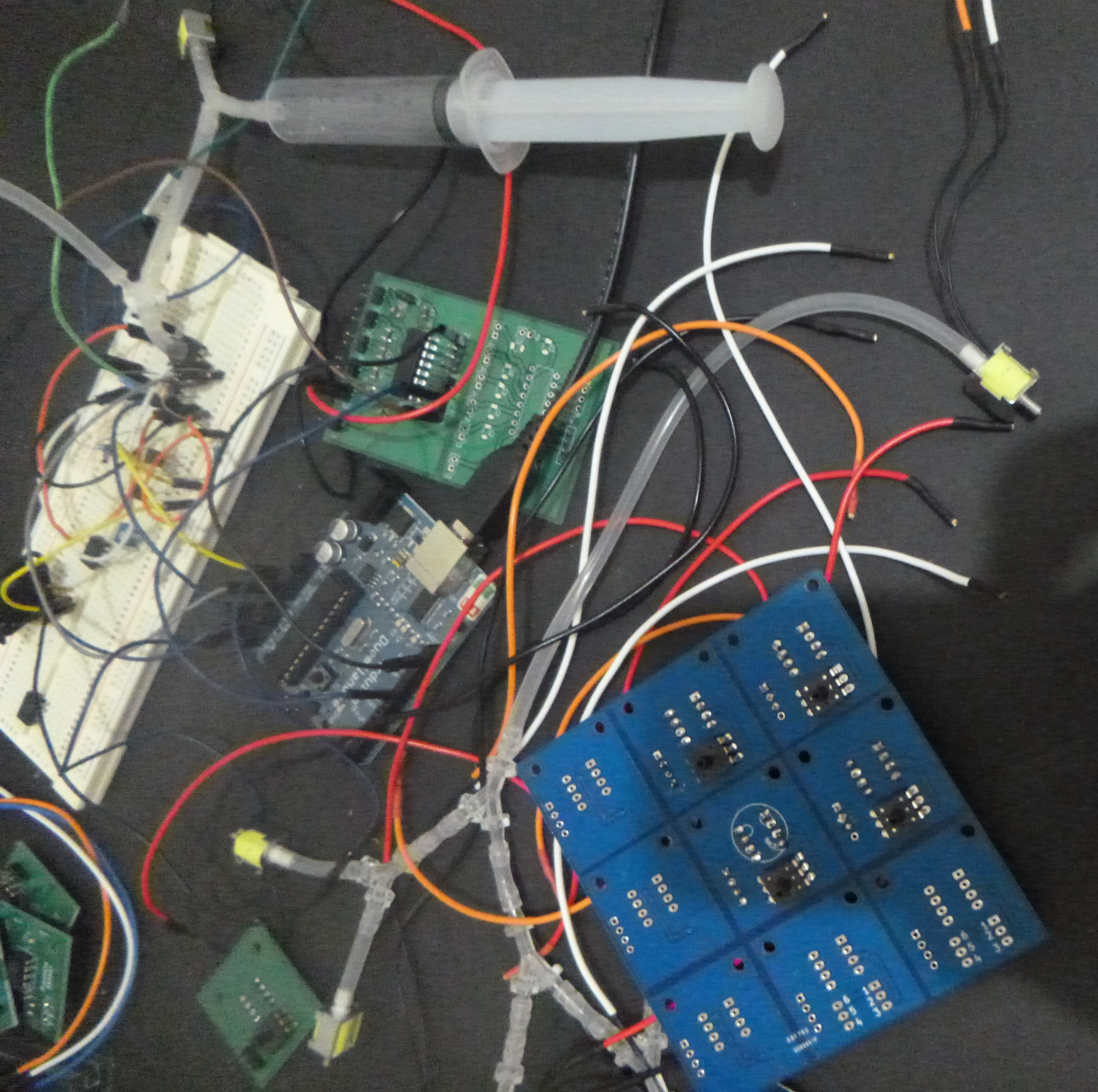
    After the physical hand is completed it needs a proper control interface. This started a few months ago sourcing appropriate components like pump, valves, connectors and pressure sensors. These have now been bread boarded and tested on a test finger.

    A background on the choices made here has largely to do with cost. A compressed CO2 setup is significantly more costly than the 6V pump and 5V values. The pressure regulation is a issue with the CO2 were as the pump's pressure is regulated via a PWM signal with a pressure sensor in feedback, however there is no reason that the hand cannot be controlled via pressurized CO2.

    For those playing along at home, the table in the picture was created to configure and calibrate the inexpensive MPS20N0040D-S pressure sensor with a MPX4250AP that has a know pressure to voltage output, but is significantly more expensive. This is in spite of the additional circuitry and amplification. The issue was that the MPS20N0040D-S is essentially a voltage divider with two output that require a difference amplifier, but it was also found that this was enough without additional amplification, the difficult to see diagram at the bottom is the sensor circuit equivalent.

    The values and pump are controlled by a high current Darlington transistor array ULN2003A linked to an Arduino.

  • Assembly of the mechanics of the hand.

    Nelson Phillips09/30/2016 at 15:15 0 comments

    Gaining the most mechanical function out of the finger required the silicone casts for the actuators to be push to the limits of my current resources. Currently these include a 3D printer and your basic two part silicone. The major problem has been getting, the perennial casters problem, bubbles in the otherwise justifiable 1mm wall thickness. This meant multiple casts of the same actuator and sometimes a repair. Finally, there is the necessary appendages to form a grip.

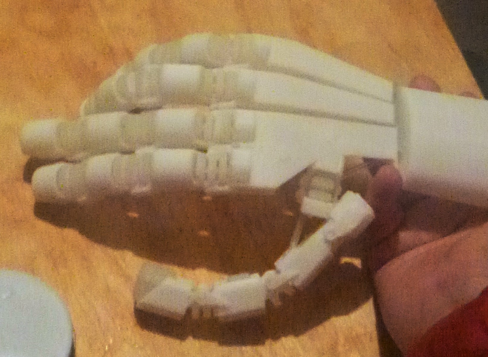
    As it is a soft (robotic) hand it is compliant with the environment, which includes gravity. The picture below is a picture of it in a "relaxed" state. When a vacuum is applied the fingers stiffen even bend back on itself, almost what some can do and have a concave back.

    Before using electronics, a pneumatic pump and values to active the hand was tested to see if it works first and then the effectiveness. However, the size of the syringe the local chemist sells is not really capable of activate three fingers to illustrate a full/partial grip, but good enough for a basic look. So the following documents the basic functions of the mechanics of the hand. More time spent maybe justifiable to create better videos, but the emphasis has been on the build making the projects assumption physically successful.

    Finally this is a view of the thumb mechanism, which is currently got a 3D printed insert for a little bit of stability and is not activate to the pressure required to achieve full function, but I think it give the idea.


  • Thumb joint and finger base

    Nelson Phillips09/26/2016 at 12:25 0 comments

    The thumb is a clearly an important component of hand function the two fingers and thumb picture below shows an early solution. It revealed that there requires an angle on the apposing joint and the third joint is a difficult to straighten from being parallel to the fingers.

    So the following two pictures show the angle and joint in detail. The two hinged joint, carried from earlier, is less restrictive and was able to provide a little more strength here.

    The actuator for the thumb base joint, below, is large and provides the force to keep it stable, using the commonly used, for this project, flexure equation

    Most of the CAD model has been completed for this stage of the project and requires construction.

  • Actuators and its exoskeleton

    Nelson Phillips09/18/2016 at 12:37 0 comments

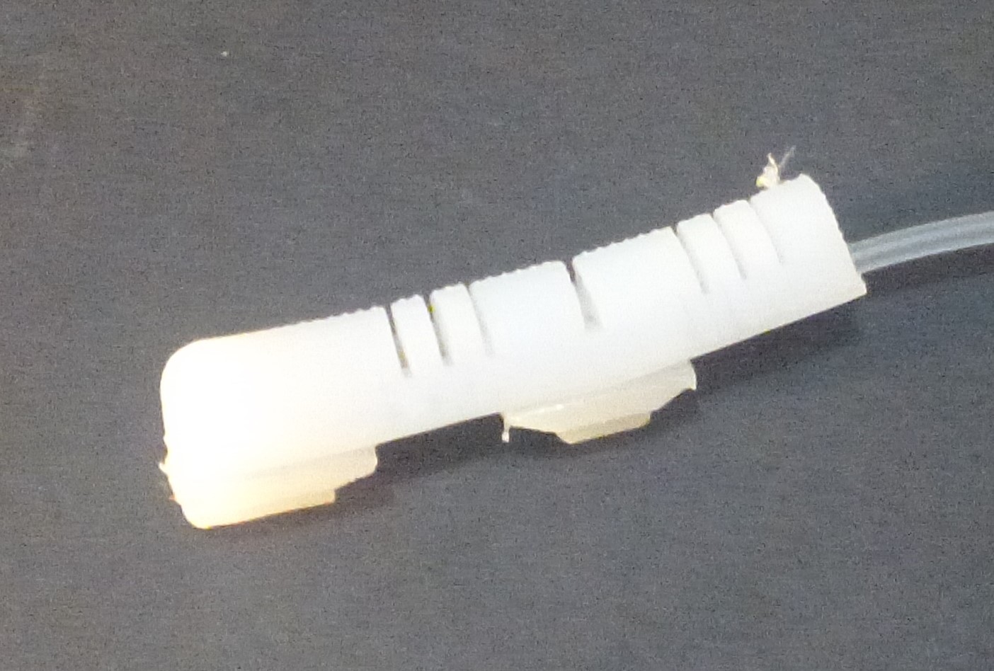
    This project started with the construction of a finger with the idea that I will work my way up the hand until it is a functional prosthesis or humanoid hand. The hand is to be constructed out of 3D printed exo-skeleton and silicone cast fingers all pneumatically controlled. This log documents how the finger has been created, but not all the many iterations before arriving at a reasonable close finish, refinement is still possible.

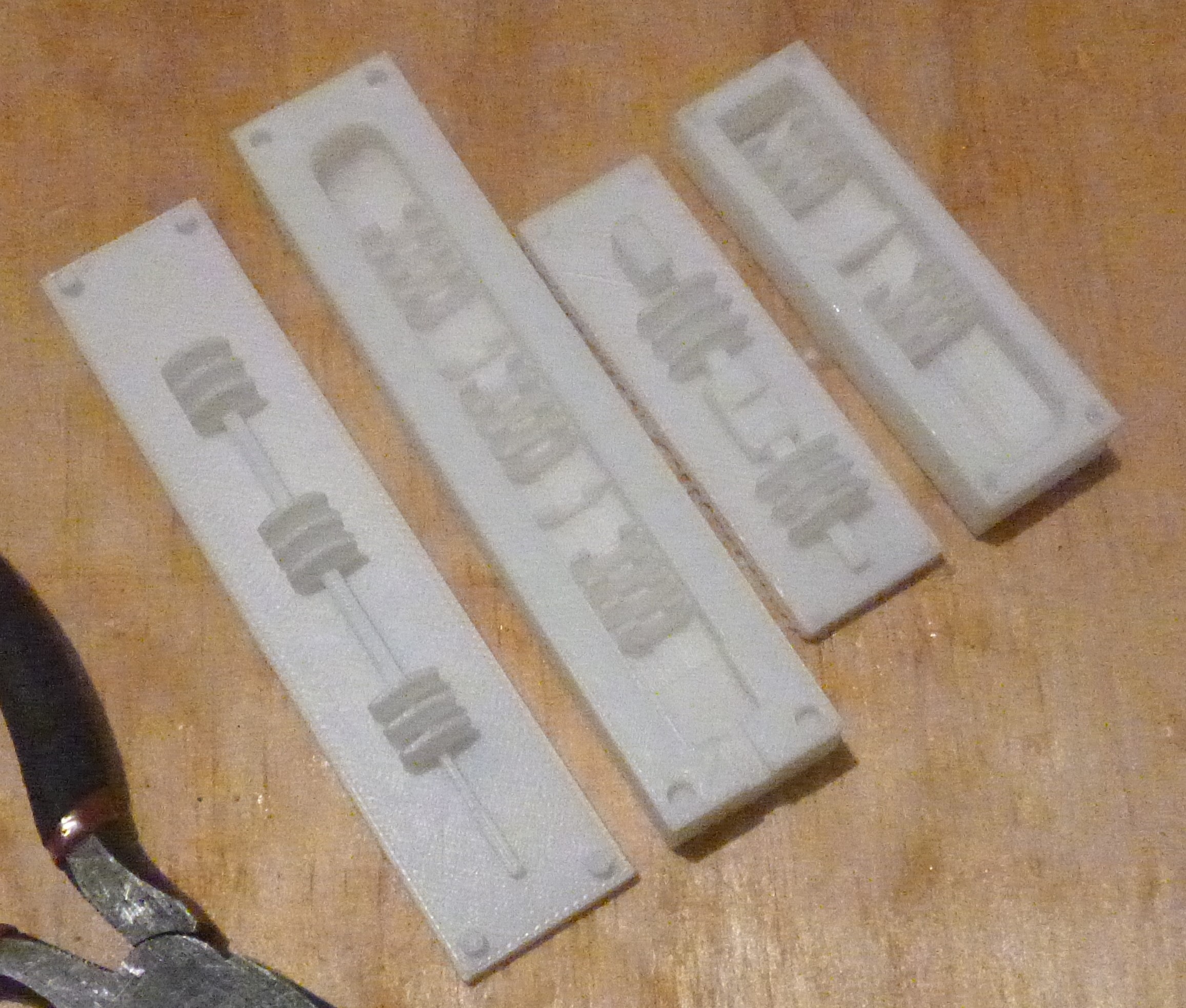
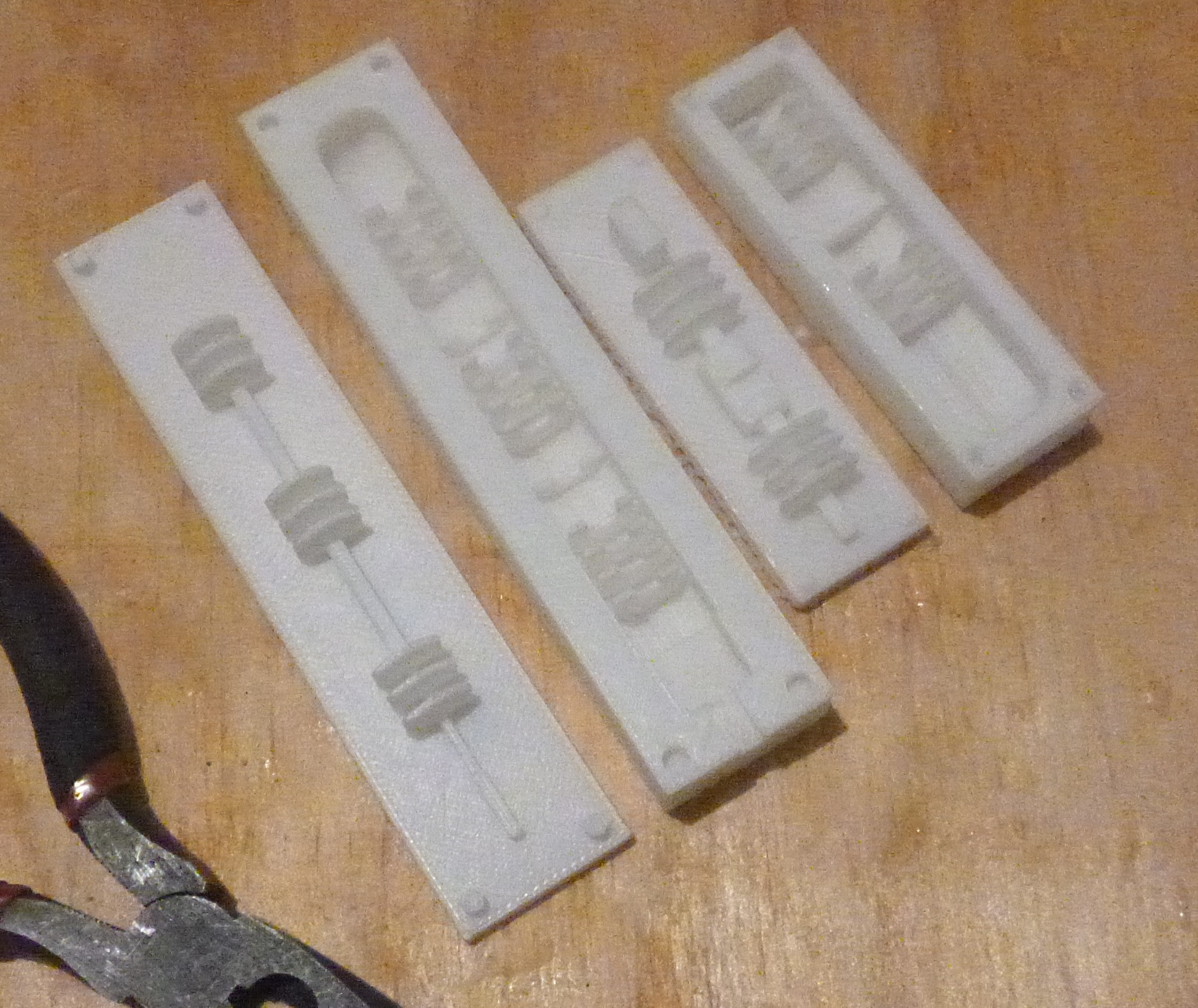
    The actuators for a soft robot/prosthetic hand are constructed out of silicone casts from 3D printed molds. The thumb and pointer/ring molds are pictured below with the actuation cavity created by the top mold being inserted into the bottom section located via location dimples.

    Pointer and Thumb top and bottom molds

    After the mold has being held together until the two part silicone has set a thin, 0.5mm 50A shore hardness strip of silicone is glued by more two part silicone or by specific glue. The harder-than-finger silicone strip acts like a flexure, reducing the bending radii and pressure required to bend the finger.

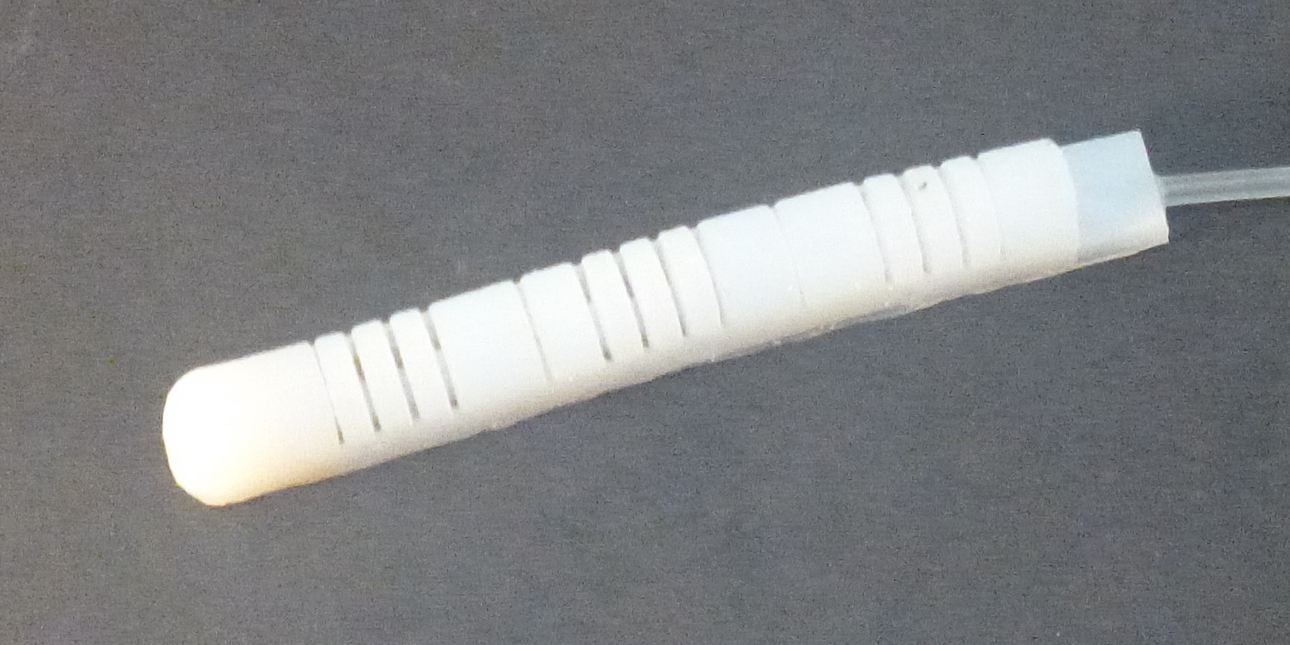
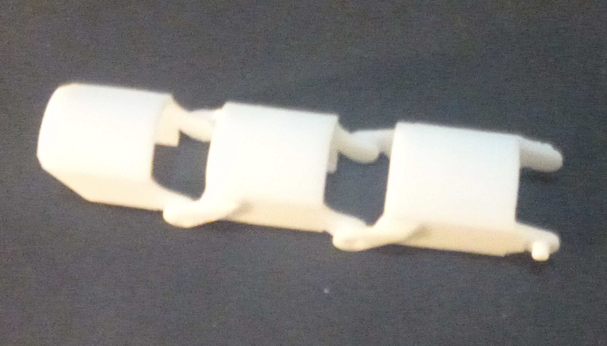
    Exoskeleton that the silicone finger sits in.

    Above is the thumb with pads on the underside, which will be implemented on all the other fingers.

View all 8 project logs

  • 1
    Step 1
    1. Mold Construction.

    Generally if you want to be inspired and create a design from scratch or modify whats available you need CAD software. There a now a plethora of choices from free opensource, FreeCAD and OpenSCAD, to brouser based and entry level software from the established market. However, the first step is that molds need to be created from stl files.

    After downloading preexisting file from GrabCAD they need to be printed. To complete a whole hand there is a total of 20 files.

    2x middle finger

    2x index and ring finger

    2x finger pads

    4x thumb and thumb pads

    4x base thumb joint

    2x wrist joint

    2x palm stability

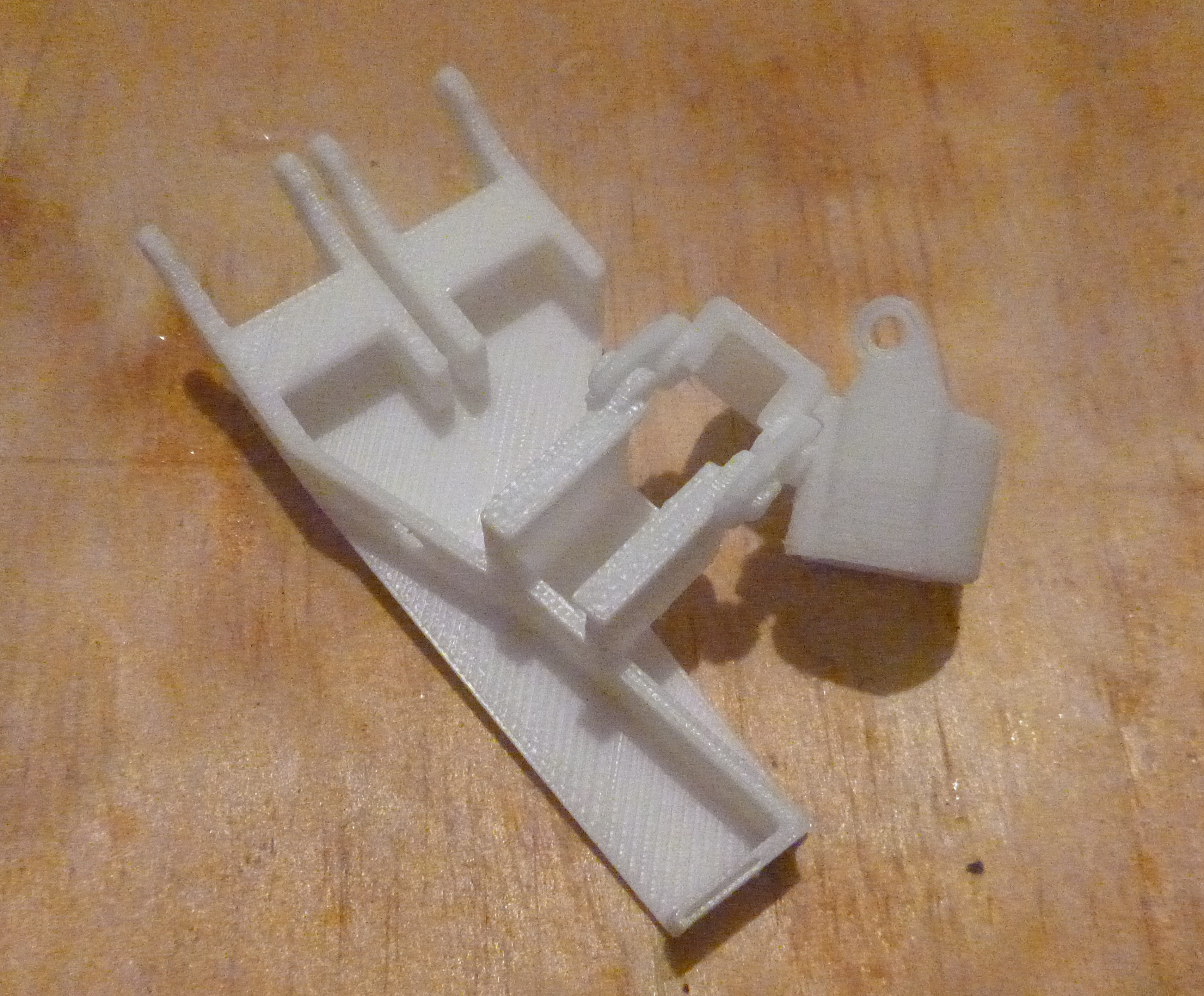
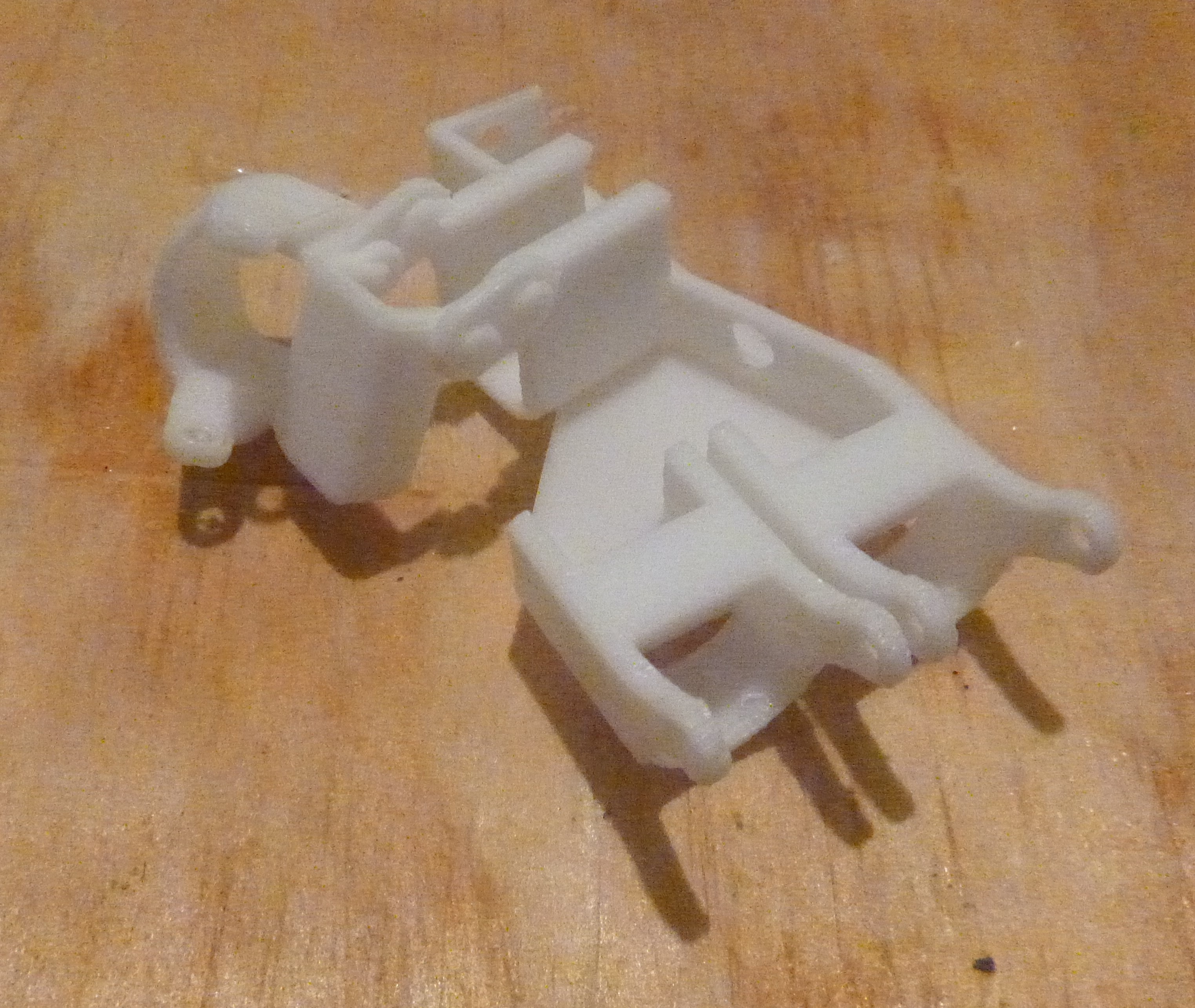
    Without having twenty pictures, the above picture shows the thumb and middle finger molds, top and bottom. These molds need to be printed in this orientation, as per the design intention.

View all instructions

Enjoy this project?

Share

Discussions

Similar Projects

Does this project spark your interest?

Become a member to follow this project and never miss any updates