 nerd.king
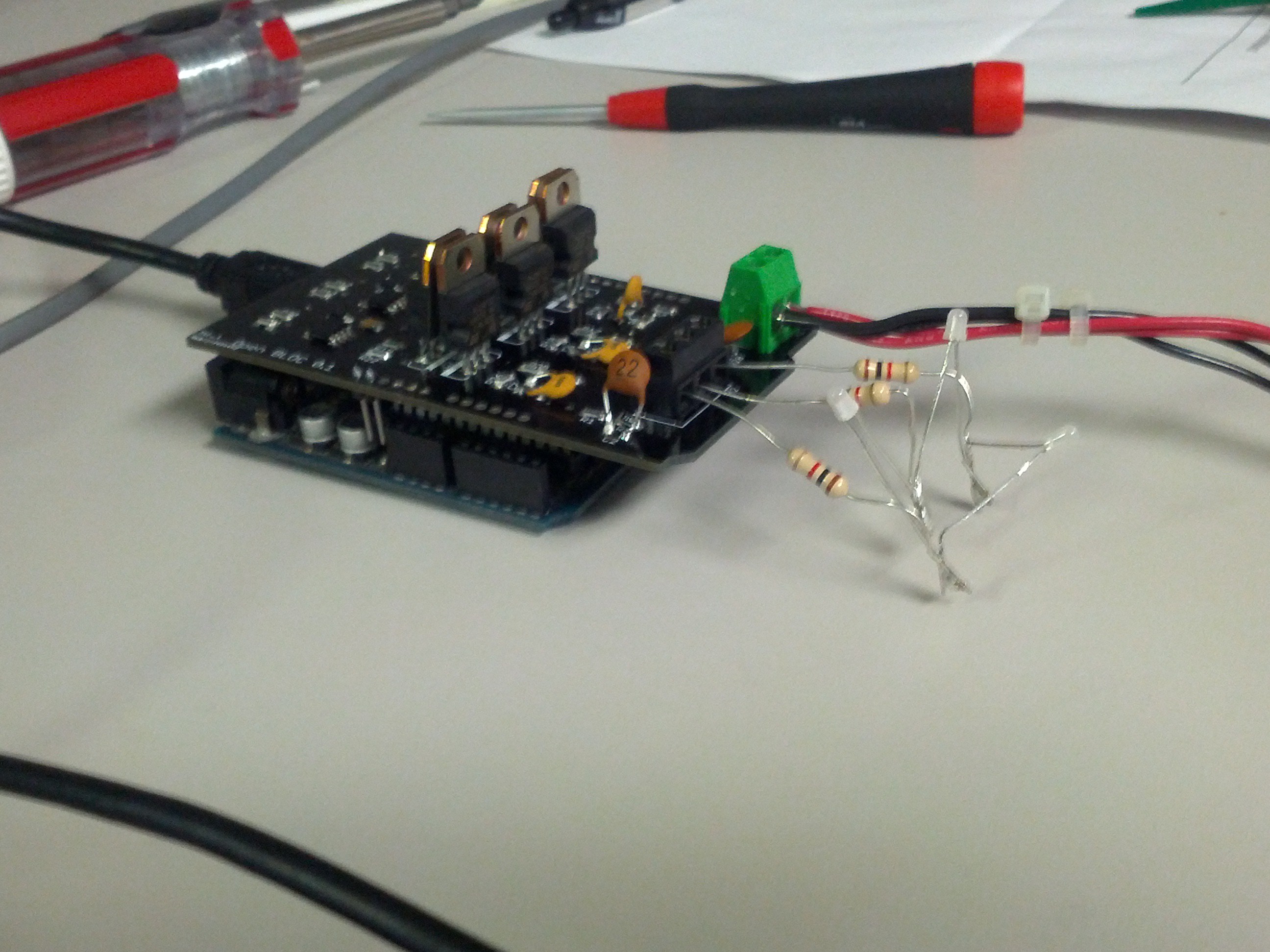
So I continue to troubleshoot the PCB. I hooked up the motor with a variable power supply and got to see the motor jitter a little bit but it caused the power supply to over current and something is just not right with the commutation stages. One of my coworkers suggested that I make a motor situlation with 3 resistors and 3 bi-color LEDS. So I hooked this up and I got 1 green, 1 red and a very weak red on the third one. The drivers seems to be getting too hot or something and shutdown after a while of running so maybe having direct access to the power supply is dangerous for these ICs. I am going to look into maybe putting a 15V regulator in between them and the 24V rail. The need 10-25volts to run but I am unsure about how much current they will try to pull especially when driving the fets.
Discussions
Become a Hackaday.io Member
Create an account to leave a comment. Already have an account? Log In.