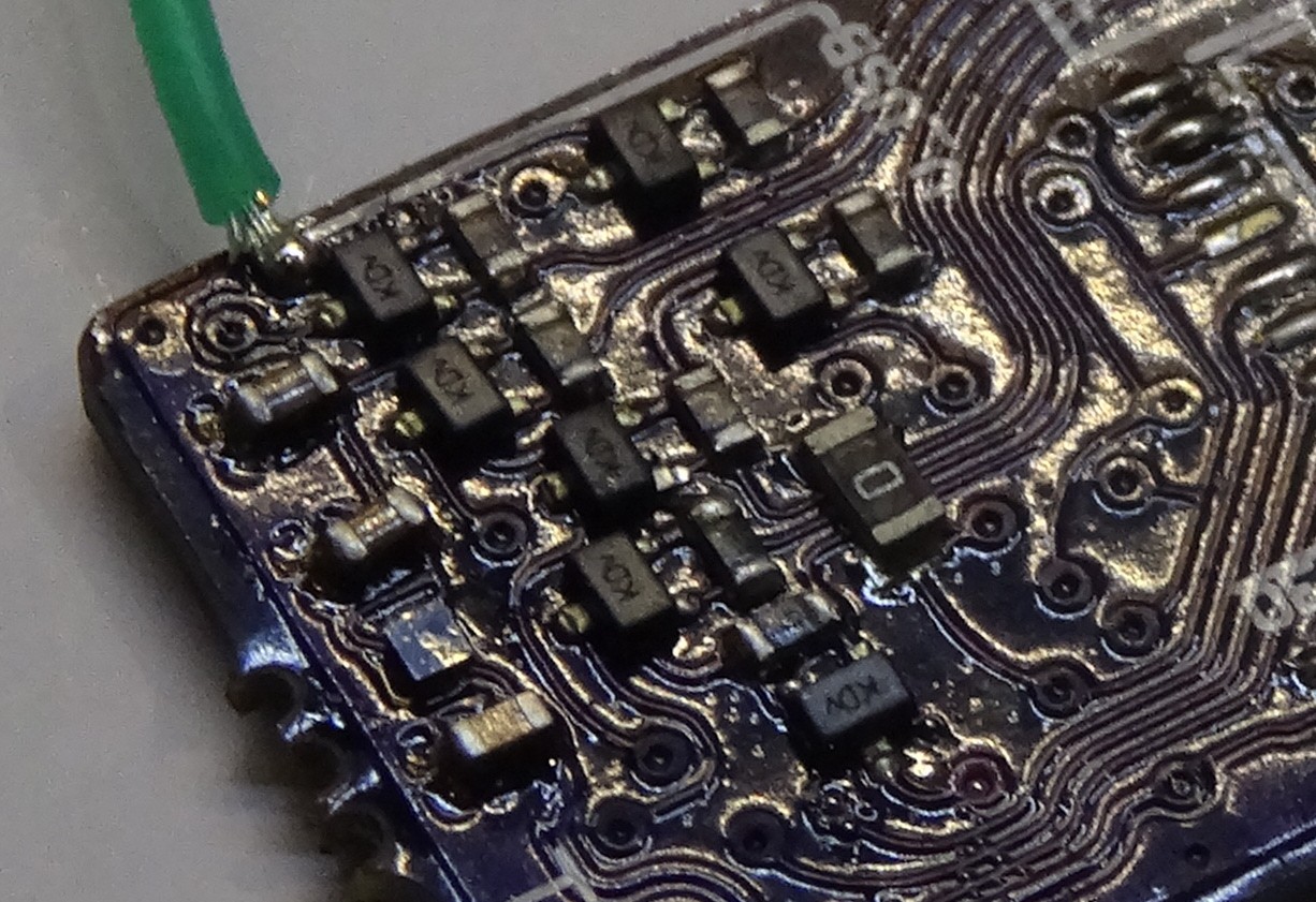
This project is still ongoing and I did received the PCBs some time ago. I also started soldering and programming. Here a picture of the line driver section of the PCB:
I also got a little bit into trouble with the LEDs. Some how I placed them all in the wrong direction in the schematic. So that the cathode marking on the PCB is now an Anode marking. The really bad thing is that I noticed that after soldering all LEDs the wrong way around.
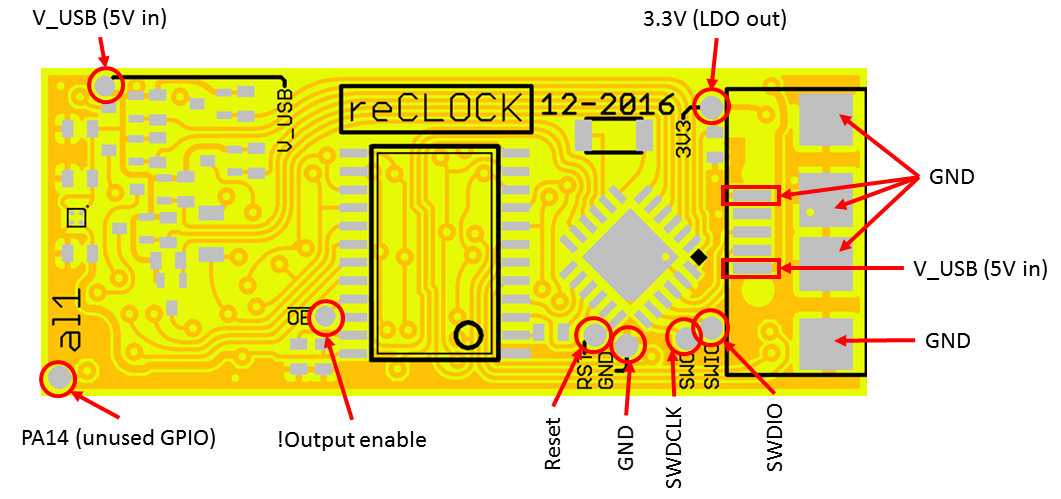
During the first programming/debugging secessions I also made this test pad overview:
 Alex
Alex

Discussions
Become a Hackaday.io Member
Create an account to leave a comment. Already have an account? Log In.