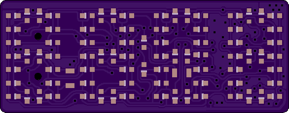
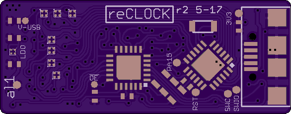
Also the first PCB, did worked. There are some issue:
- It could only run on 3.3V because of a mistake with the p-fets
- The footprint of the LEDS were so much undersized, that soldering was quite difficult an unreliable
- The TSSOP package of the shift register looks to big
As Solution a made a new revision:
- Now with smart integrated high-side switches (TPS22912 or similar) and because of these with more BGA parts
- Bigger Solder pads for LEDs. Some new routing was needed, because now only one trace fits under each LED. But OSH-Park's new 10mil Drills helps a lot.
- the shift register is now also QFN.
Here some preview of the boards:


 Alex
Alex
Discussions
Become a Hackaday.io Member
Create an account to leave a comment. Already have an account? Log In.