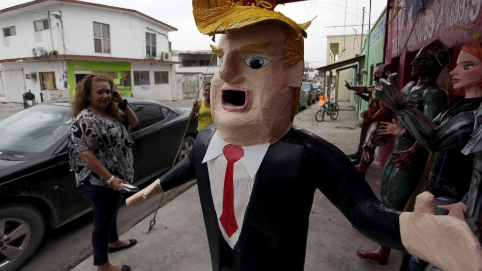
hits on the piñata are monitored by an accelerometer tied to a teensy uController that plays back stupid audio clips stored on an SD card. A nodeMcu also broadcasts the accelerometer hits in g's to data.sparkfun.com
Adafruit's 200G accelerometer (ADXL377) can measure hits up to 200g's. I'm totaling the analog inputs from x, y, and z. You supply 3volts from the teens to the VIN pin on the accelerometer.
1×
200g accelerometer
I used a 200g accelerometer to get accurate hit data... you could easily use a cheaper accelerometer if you are not interested in accuracy... https://www.adafruit.com/product/1413
The teensy continuously reads the accelerometer and trigger audio output random WAV files on the SD card. The nodeMcu posts the 'hits' on the pinata to data.sparkfun.com and graphs it at http://analog.io/sADI
**I started this project with the PJRC's prop_shield. It fits on the teensy uController. The prop shield is great for broadcasting in a small quite place through a small speaker. During the party we opted to run a 1/8" jack from the teensy audio shield to an amplifier to make it terribly loud.... If you go that route, you don't need the prop_shield... It's kind of fun to cut a hole in trump though..
2
Step 2
Solder your components....
Use the longest headers you can find or an assortment of male headers and female headers (safer/easier for troubleshooting) to sandwich the teensy between the prop_shield and the audio shield....
Above is shown the prop shield on the bottom of a teensy uController.
Above is shown the Audio shield on top of the teensy.
Above is essentially the same thing accept with female and male headers. The advantage to this setup is you can easily take it apart for troubleshooting. The disadvantage is it is quite a bit more bulky but you'll have plenty of space in the pinata.
Finally the accelerometer needs to be soldered or connected to the uController analog inputs. I used three analog inputs for a big 200G accelerometer. If you are not interested in measuring exact magnitude of 'hits' you may use a cheaper accelerometer and read it over i2C or something similar.
Although it's hard to tell in this picture, I connected the accelerometer as follows:
teensy => accelerometer 3.3 pad to Vin (accelerometer) gnd pad to gnd A15 pad to zAxis accelerometer A16 pad to yAxis A17 pad to zAxis
To connect the nodeMcu, simply connect the teensy Serial1 TX1 (pin 1) to the RX pin on the nodeMcu. You also need to connect ground and may also want to share power by matching the Vin pins or 3.3 pin (don't mix them!)...