 f4hdk
f4hdk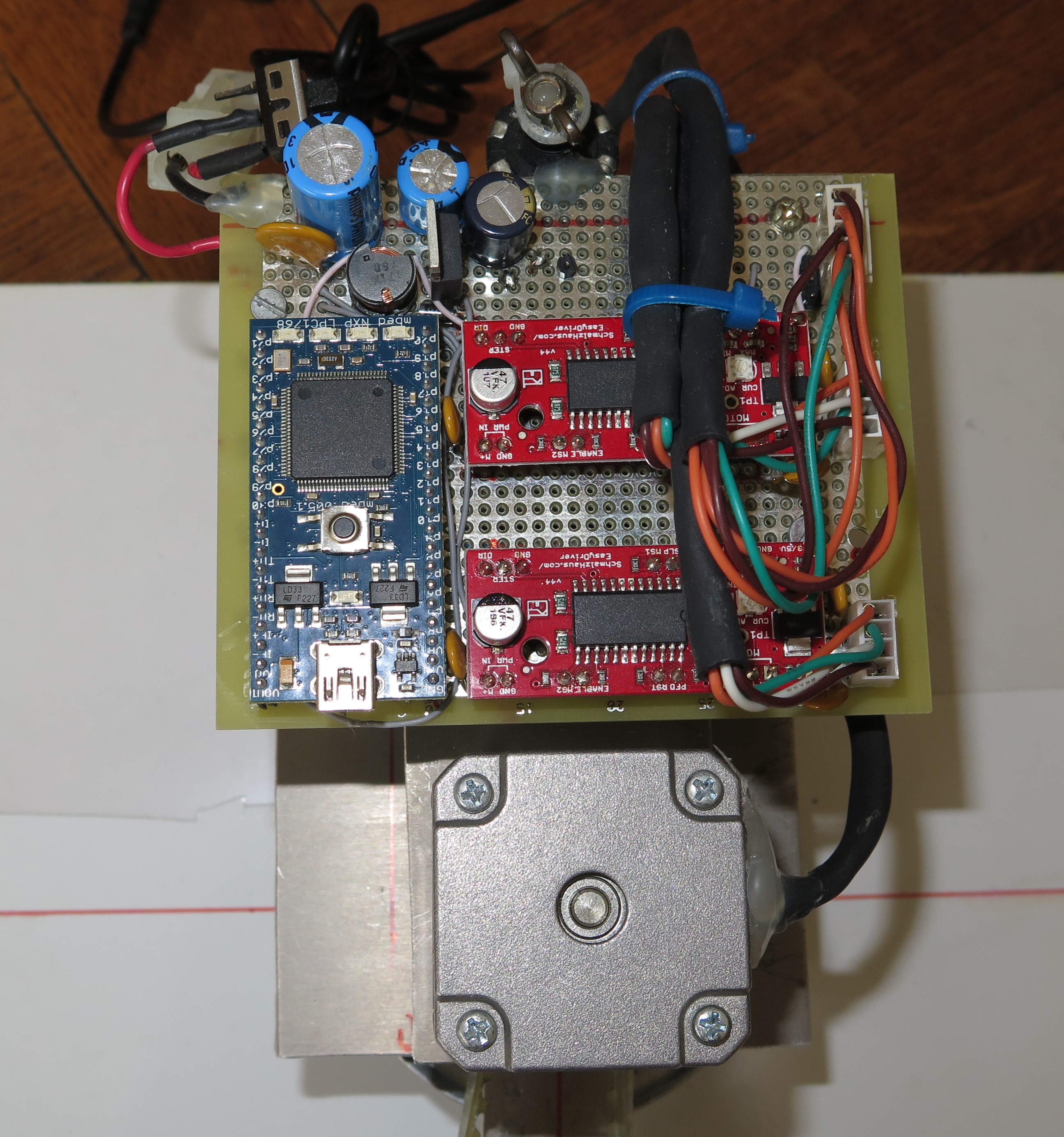
The electronic part of this project is quite simple.
- One Mbed microcontroller board, with LPC1789 (ARM Cortex M3)
- 2 x stepper motor controller boards “easy driver” from Sparkfun, equipped with A3967
- A 5V switching regulator (for both wrist servo and microcontroller)
- One potentiometer which value is read by microcontroller. The user can tune the movement speed with it.
- One servo output for the wrist (servo signal is directly generated by GPIO from Mbed)
- 2 digital inputs for the end-stroke micro switch (needed because stepper motors do not know their absolute position)
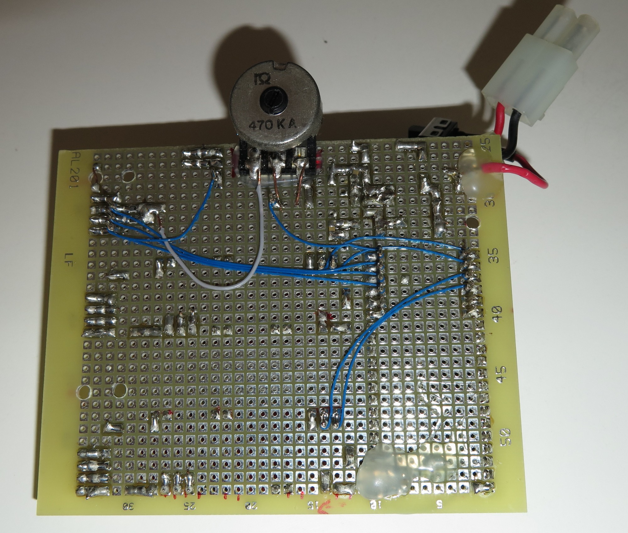
The board I use is wire-wrapped, but you can use another solution.
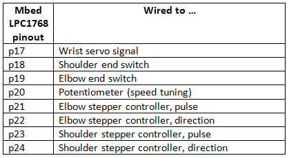
Wiring Diagram
Remarks
The stepper motor controllers are quite powerful. For just a few dollars, you can have lots of features inside : bi-polar motor compatible, with H-bridge inside, without the need of freewheeling diodes, and optimised for thermal dissipation, with current regulation, and last but not least micro-steps. This greatly reduces the amount of code and the amount of electronic components, compared to stepper motor controllers which were available in the 90s.
The robot is powered with 24V, even if the motors are 12V. We can do it because the stepper motor controllers regulate the current they inject inside the motors. Higher voltage is necessary if you want to use stepper motors at quite high speeds.
Discussions
Become a Hackaday.io Member
Create an account to leave a comment. Already have an account? Log In.