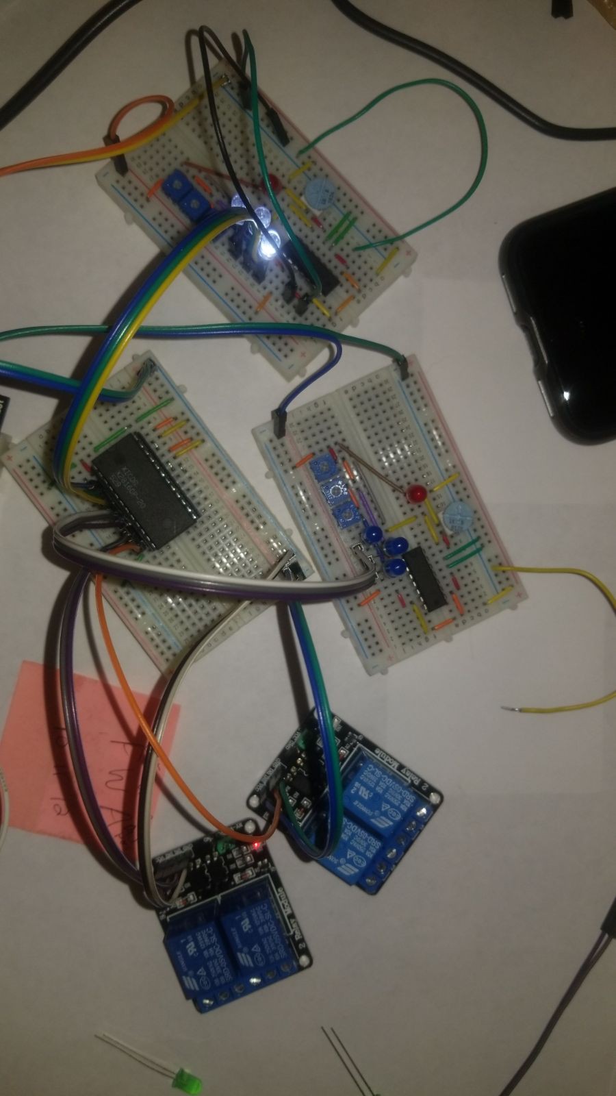
The input comparator circuits, EEPROM, and output relays were connected together and tested prior to interfacing them with the security panel.
Note the later revision of the comparator circuit. Here the power LED is also generating the reference voltage for the other comparator inputs. Potentiometers are used to fine-tune the voltage at the indicator LEDs to a range appropriate for the LEDs selected (here blue & white 3.3V forward voltage LEDs).
The test leads wired to ground on the topmost comparator are simply meant to represent a zero (0) voltage closed switch input.

 Jon
Jon
Discussions
Become a Hackaday.io Member
Create an account to leave a comment. Already have an account? Log In.