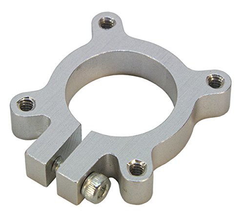
Over the past few days I've been mulling over ways to reduce the cost, complexity and width of the joints. Pictures of my current design show joint 3 - you can see in the pictures that the joint is quite wide due to the kind of hardware I'm using for holding bearings in place (clamping hubs):

The clamping hubs are tightened around the OD of the 608ZZ bearings, which are bonded to the shaft. This is not the intended usage for these hubs (they are designed for clamping onto a length of tube). Additionally, they are overpriced and not widely stocked.
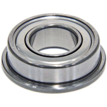
I have decided to replace these clamping hubs with low-cost F688ZZ flanged bearings that will be bonded to the shaft, and press-fit into the CF frame:

These bearings are somewhat narrower than the 608ZZ bearings, and will sit within the walls of the frame. For walls with a 4mm thickness, these bearings will only add 1.1mm width once fitted (compared to the additional ∼10mm width of the clamping hubs).
The top and bottom plates of the frame will constrain the collars/bearings laterally so that there is no side-to-side slipping on the shaft.
This design will make belt replacement a little bit more involved (i.e. the user would need to partially disassemble the frame to be able to replace a belt), but I think the benefits vastly outweigh this minor inconvenience.
I will also be modifying the design so that the arrangement of each joint is a lot neater, and more similar to the design of commercial robotic arms.
I will publish a new design reflecting these changes soon.
Please feel free to comment about any design ideas you have... you might spot something I've missed, or have an idea that greatly improves the performance of the design.
 David Shelenev
Discussions
Become a Hackaday.io Member
Create an account to leave a comment. Already have an account? Log In.