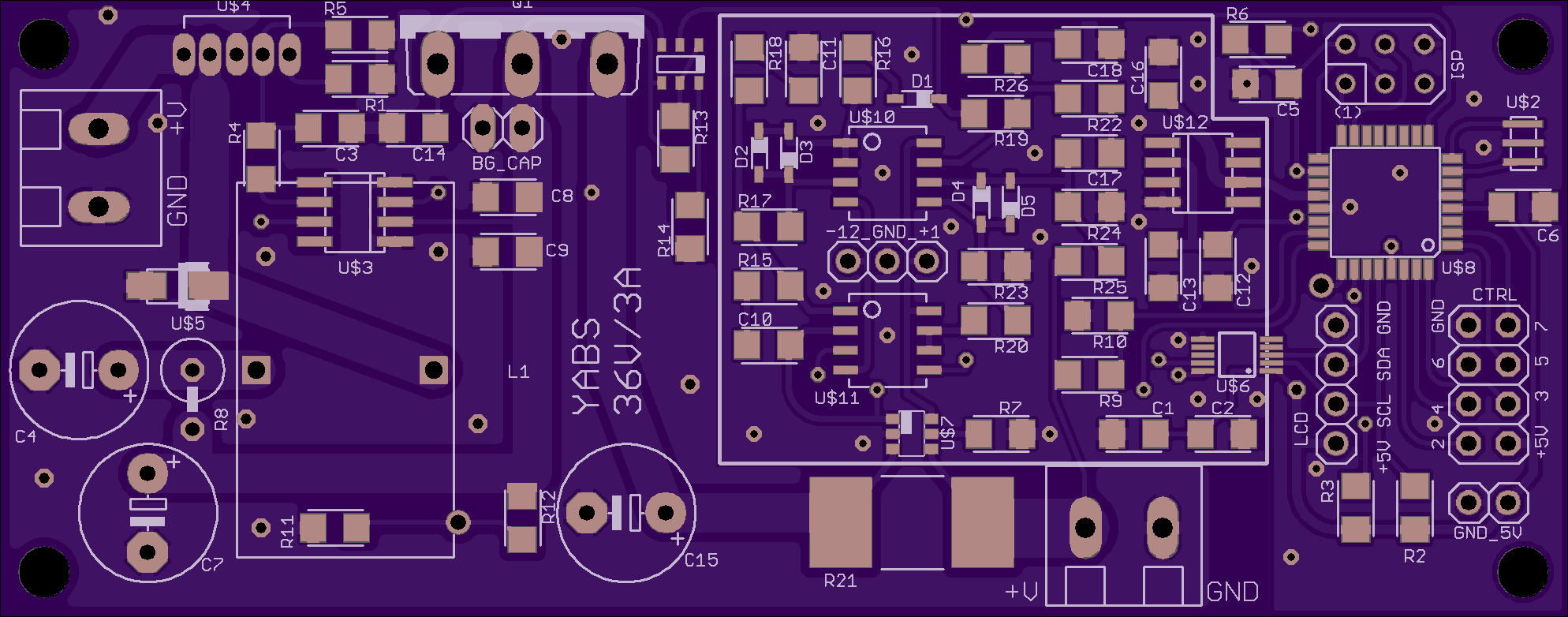
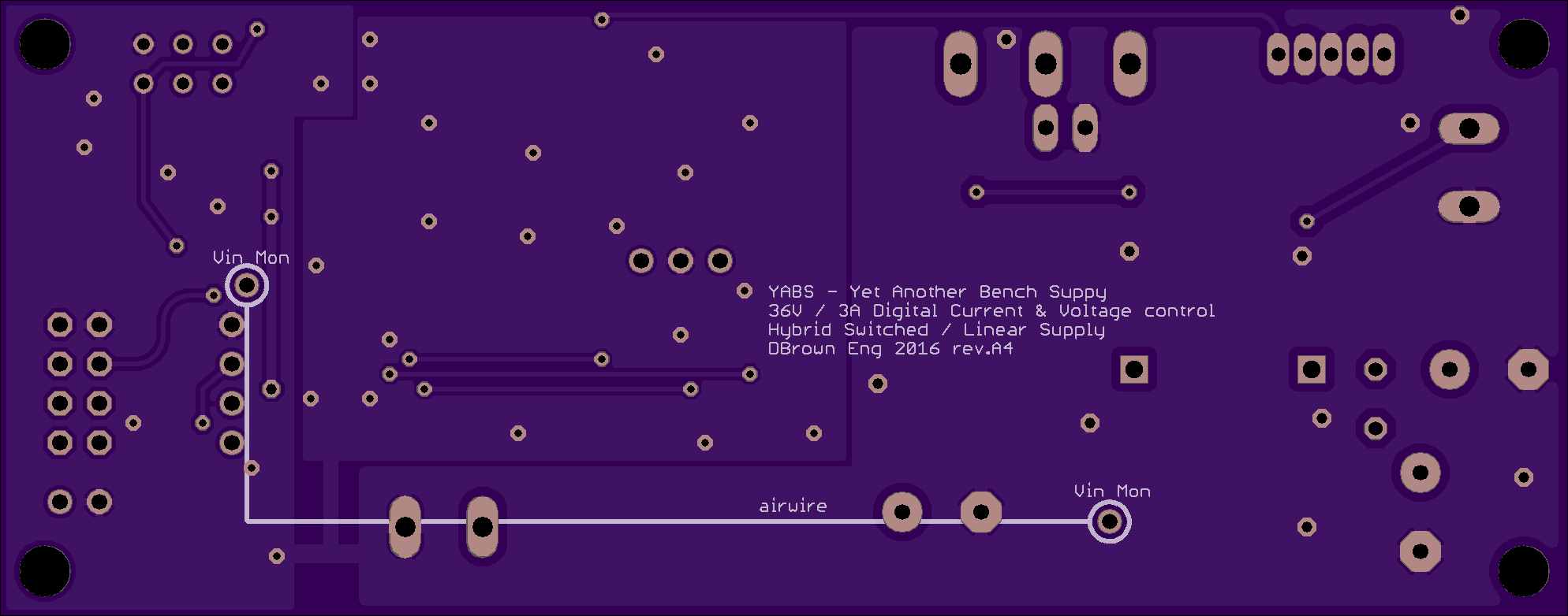
I've been playing with the design some more, and moved the large capacitor off the board. The linear control section was then relaid and separate grounds introduced for the analogue, digital and power sections.
Finally I've added a voltage difference section that maintains a constant 3v higher output of the switched section compared to the linear section using a difference amplifier than can be run off the max 36v input voltage.
The BOM cost is higher than expected, but the aim is for something that will last a few decades, board size is ~100x40mm.


 David Brown
Discussions
Become a Hackaday.io Member
Create an account to leave a comment. Already have an account? Log In.