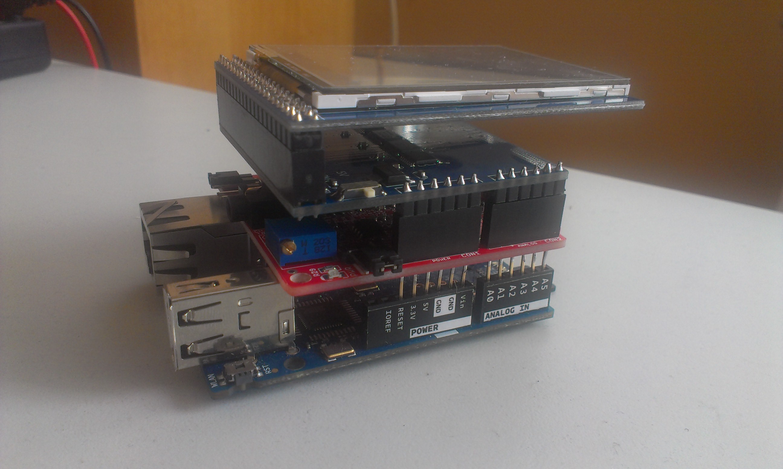
How about we plug EKG-EMG shield into Arduino Yun, and stack an LCD touch screen on top of it?
That device could:
- publish to internet in real-time
- provide touch-screen user interface
- display the reading
I played a bit with it. To make long story short, let me jump to conclusions.
Good stuff:
LCD is quite handy, for you need to be still during measurement.
EKG-EMG shield allows to select input pins, so it's fully stackable, and does not interfere with other shields
With some power supply, this could really be a DIY IoT ECG, fully portable, able to store data to SD card too.
Yun also has enough CPU power to filter and display the data, and supports any programming language of choice.
Bad stuff:
Touch screen is pretty much useless, for it is too small. Any UI components large enough to press them, don't leave enough space to display actual readings. Furthermore, touch is interrupt, ECG is interrupt, and displaying the data takes time - all that makes development considerably harder. Bottom line - better give up touch screen and use simple buttons.
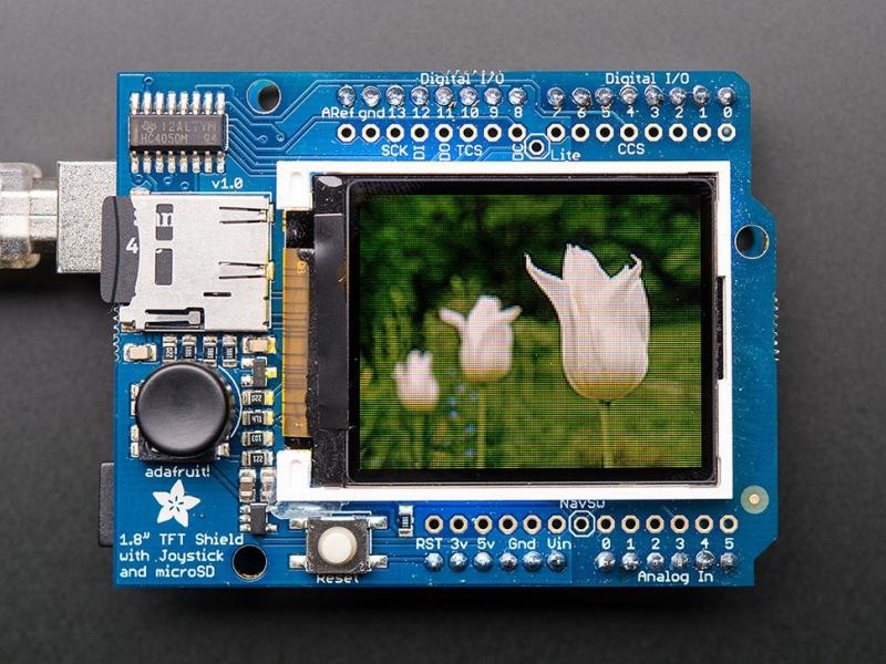
Or, here's what I'd ideally put on top:

Anyway, we'll are going to plug cardiotron to PC, so I don't intend to purse this further.
Here's some code in case anyone's interested.
#include <UTFT.h>
#include <UTouch.h>
#include <compat/deprecated.h>
#include <FlexiTimer2.h>

// EKG STUFF
// All definitions
#define NUMCHANNELS 6
#define HEADERLEN 4
#define PACKETLEN (NUMCHANNELS * 2 + HEADERLEN + 1)
#define SAMPFREQ 256                      // ADC sampling rate 256
#define TIMER2VAL (1024/(SAMPFREQ))       // Set 256Hz sampling frequency
#define LED1  13
#define CAL_SIG 9

// Global constants and variables
volatile unsigned char TXBuf[PACKETLEN];  //The transmission packet
volatile unsigned char TXIndex;           //Next byte to write in the transmission packet.
volatile unsigned char CurrentCh;         //Current channel being sampled.
volatile unsigned char counter = 0;	  //Additional divider used to generate CAL_SIG
volatile unsigned int ADC_Value = 0;	  //ADC current value

// LCD STUFF
// Declare which fonts we will be using
extern uint8_t SmallFont[];

// Set the pins to the correct ones for your development shield
UTFT myGLCD(ITDB24E_8,A5,A4,A3,A2);
UTouch  myTouch( 15,10,14, 9, 8 );

// JOE's stuff
int sequence = 0;
volatile unsigned int values[6];
int prev1 = 0;
int prev2 = 0;
int prev3 = 0;
unsigned int  touchX, touchY;

void setup() {
  setupLCD();
  setupTouch();
  setupEKG();
}
void setupTouch() {
  myTouch.InitTouch();
  myTouch.setPrecision(PREC_MEDIUM);
}
void setupEKG() {
  noInterrupts();  // Disable all interrupts before initialization
  // LED1
  pinMode(LED1, OUTPUT);  //Setup LED1 direction
  digitalWrite(LED1,LOW); //Setup LED1 state
  pinMode(CAL_SIG, OUTPUT);
  //Write packet header and footer
  TXBuf[0] = 0xa5;    //Sync 0
  TXBuf[1] = 0x5a;    //Sync 1
  TXBuf[2] = 2;       //Protocol version
  TXBuf[3] = 0;       //Packet counter
  TXBuf[4] = 0x02;    //CH1 High Byte
  TXBuf[5] = 0x00;    //CH1 Low Byte
  TXBuf[6] = 0x02;    //CH2 High Byte
  TXBuf[7] = 0x00;    //CH2 Low Byte
  TXBuf[8] = 0x02;    //CH3 High Byte
  TXBuf[9] = 0x00;    //CH3 Low Byte
  TXBuf[10] = 0x02;   //CH4 High Byte
  TXBuf[11] = 0x00;   //CH4 Low Byte
  TXBuf[12] = 0x02;   //CH5 High Byte
  TXBuf[13] = 0x00;   //CH5 Low Byte
  TXBuf[14] = 0x02;   //CH6 High Byte
  TXBuf[15] = 0x00;   //CH6 Low Byte
  TXBuf[2 * NUMCHANNELS + HEADERLEN] =  0x01;	// Switches state

  // Timer2
  // Timer2 is used to setup the analag channels sampling frequency and packet update.
  // Whenever interrupt occures, the current read packet is sent to the PC
  // In addition the CAL_SIG is generated as well, so Timer1 is not required in this case!
  FlexiTimer2::set(TIMER2VAL, Timer2_Overflow_ISR);
  FlexiTimer2::start();

  // Serial Port
  Serial.begin(57600);
  //Set speed to 57600 bps

  // MCU sleep mode = idle.
  //outb(MCUCR,(inp(MCUCR) | (1<<SE)) & (~(1<<SM0) | ~(1<<SM1) | ~(1<<SM2)));

  interrupts();  // Enable all interrupts after initialization has been completed
}

void setupLCD() {
// Setup the LCD
  myGLCD.InitLCD();
  myGLCD.setFont(SmallFont);
  initScreen();
  drawScreen();
}

// blink the led during transfer
void Toggle_LED1(void) {
  if((digitalRead(LED1))==HIGH){ digitalWrite(LED1,LOW); }
  else{ digitalWrite(LED1,HIGH); }
}

// switch over cal-sig - CHECKME
void toggle_GAL_SIG(void) {
  if(digitalRead(CAL_SIG) == HIGH){ digitalWrite(CAL_SIG, LOW); }
  else{ digitalWrite(CAL_SIG, HIGH); }
}

// timer interrupt handler - measure and transfer
void Timer2_Overflow_ISR() {
  // Toggle LED1 with ADC sampling frequency /2
  Toggle_LED1();

  //Read the 6 ADC inputs and store current values in Packet
  for(CurrentCh=0;CurrentCh<6;CurrentCh++){
    ADC_Value = analogRead(CurrentCh);
    values[CurrentCh] = ADC_Value;
    TXBuf[((2*CurrentCh) + HEADERLEN)] = ((unsigned char)((ADC_Value & 0xFF00) >> 8));	// Write High Byte
    TXBuf[((2*CurrentCh) + HEADERLEN + 1)] = ((unsigned char)(ADC_Value & 0x00FF));	// Write Low Byte
  }

  drawValues();
  sequence++;
  if ( sequence >= 320 ) {
    sequence = 0;
    //drawScreen();
  }


  // Send Packet
  for(TXIndex=0;TXIndex<17;TXIndex++){
    Serial.write(TXBuf[TXIndex]);
  }

  // Increment the packet counter
  TXBuf[3]++;

  // Generate the CAL_SIGnal
  counter++;		// increment the devider counter
  if(counter == 12){	// 250/12/2 = 10.4Hz ->Toggle frequency
    counter = 0;
    toggle_GAL_SIG();	// Generate CAL signal with frequ ~10Hz
  }
}

void initScreen() {
  myGLCD.clrScr();

  myGLCD.setColor(255, 255, 0);
  myGLCD.fillRect(0, 0, 319, 13);
  myGLCD.setColor(0,0,0);
  myGLCD.setBackColor(255, 255, 0);
  myGLCD.print("DIY ECG - Joe's Free Stuff", CENTER, 1);
  drawScreen();
}
void drawScreen() {
  myGLCD.setColor(0, 0, 0);
  myGLCD.fillRect(0, 14, 319, 239);
// Draw crosshairs
  myGLCD.setColor(0, 0, 255);
  myGLCD.drawRect(0, 15, 319, 224);

  myGLCD.setColor(0, 0, 255);
  myGLCD.setBackColor(0, 0, 0);
  myGLCD.drawLine(159, 15, 159, 224);
  myGLCD.drawLine(1, 119, 318, 119);
  for (int i=9; i<310; i+=10)
    myGLCD.drawLine(i, 117, i, 121);
  for (int i=19; i<220; i+=10)
    myGLCD.drawLine(157, i, 161, i);

}

void drawValues() {
  int lead1 = values[0] - values[1];
  int lead2 = values[2] - values[1];
  int lead3 = values[2] - values[0];
  // clear current position
  myGLCD.setColor(0,0,0);
  myGLCD.drawLine(sequence,14,sequence,239);
  // draw lead 1
  myGLCD.setColor(255, 255, 255);
  if ( sequence > 0 ) {
    myGLCD.drawLine(sequence-1, prev1/5+60, sequence, lead1/5+60);
  }

  // draw lead 2
  myGLCD.setColor(255, 255, 0);
  if ( sequence > 0 ) {
    myGLCD.drawLine(sequence-1, prev2/5, sequence, lead2/5);
  }
  // draw lead 3
  myGLCD.setColor(0, 255, 255);
  if ( sequence > 0 ) {
    myGLCD.drawLine(sequence-1, prev3/5+20, sequence, lead3/5+20);
  }
  prev1 = lead1;
  prev2 = lead2;
  prev3 = lead3;

  if ( touchX != -1 || touchY != -1 ) {
    //myGLCD.print("DIY ECG - Joe's Free Stuff", CENTER, 1);
    myGLCD.setColor(255, 255, 255);
    myGLCD.drawLine(0,0,touchX,touchY);
    touchX = -1;
    touchY = -1;
  }
}

void loop() {
  __asm__ __volatile__ ("sleep");
} mikrotron
Discussions
Become a Hackaday.io Member
Create an account to leave a comment. Already have an account? Log In.