 oneohm
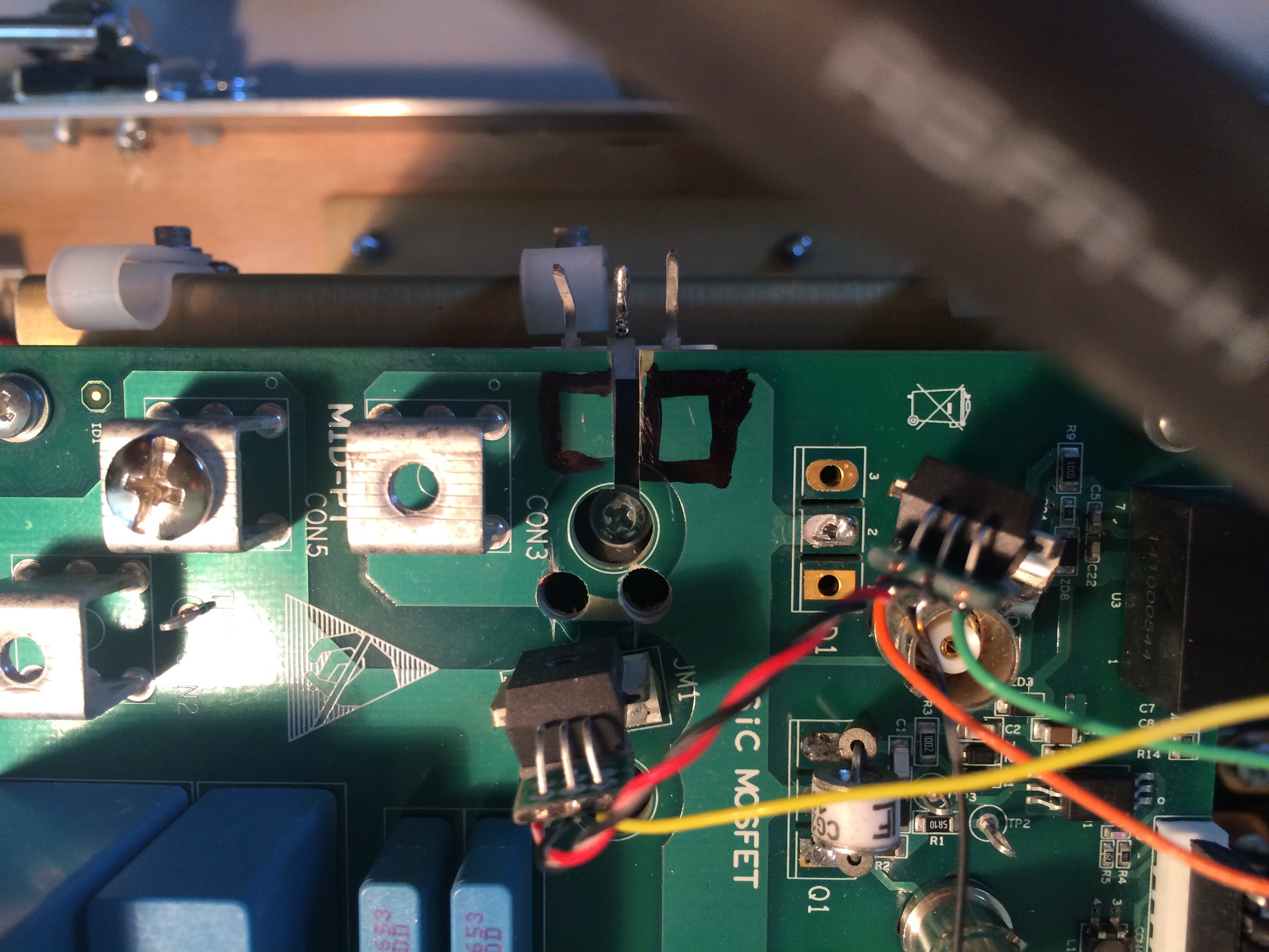
To monitor the current I modified the boards to accept some Allegro high current sensor ICs.
http://www.allegromicro.com/en/Products/Current-Sensor-ICs/Fifty-To-Two-Hundred-Amp-Integrated-Conductor-Sensor-ICs.aspx

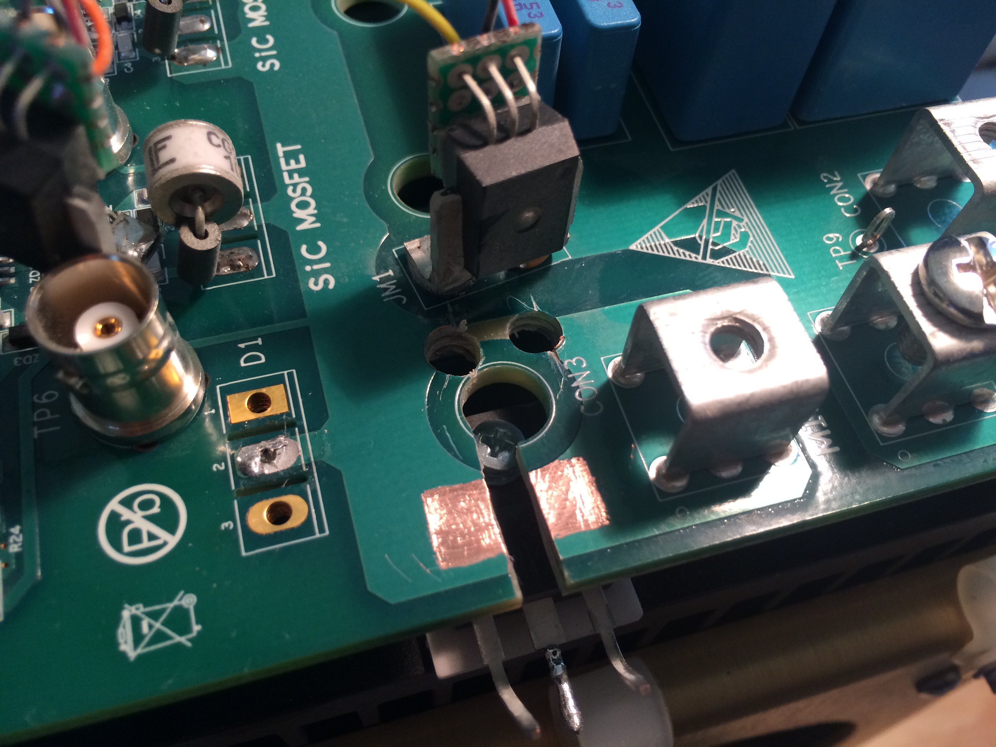
This turned out to be more difficult that just cutting a trace as power was also being routed on some of the internal layers. Two carefully drilled holes and a slot cut through the board. These were later insulated with some clear acrylic sealant (nail polish).
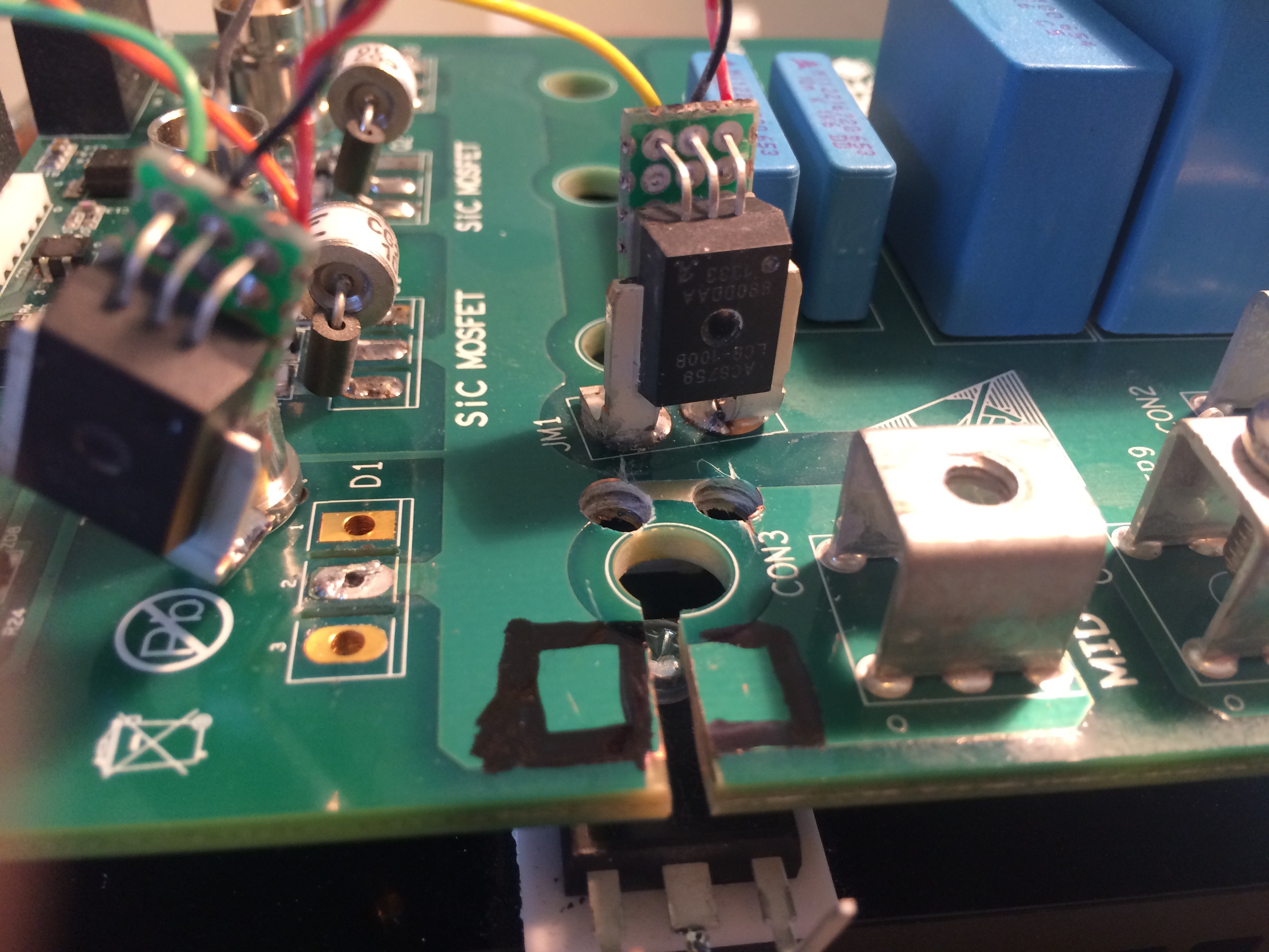
 Another angle:
 I carefully removed the solder mask to create a footprint for the second current sensor:
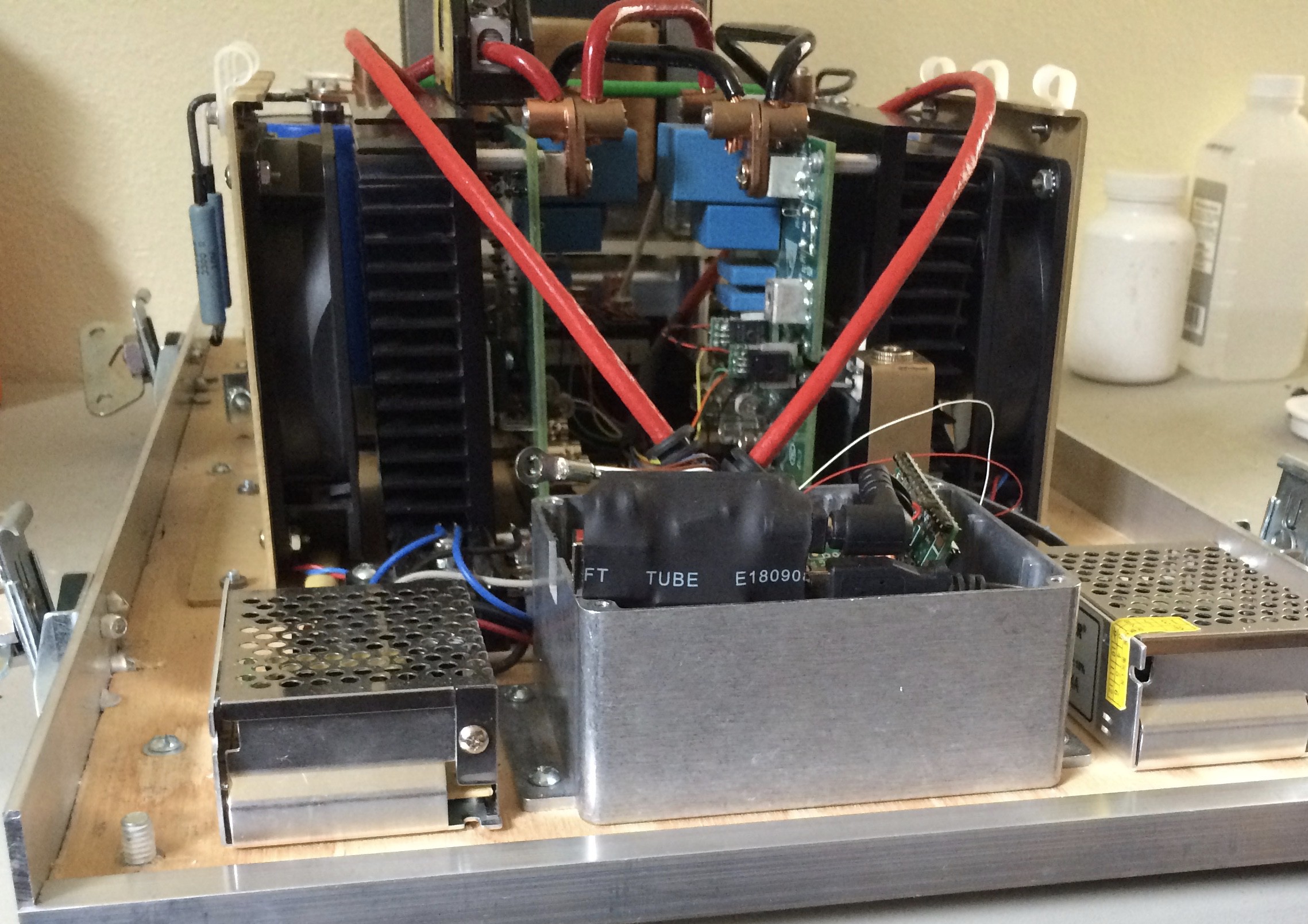
 Here you can see them mounted to the module on the right:
Discussions
Become a Hackaday.io Member
Create an account to leave a comment. Already have an account? Log In.