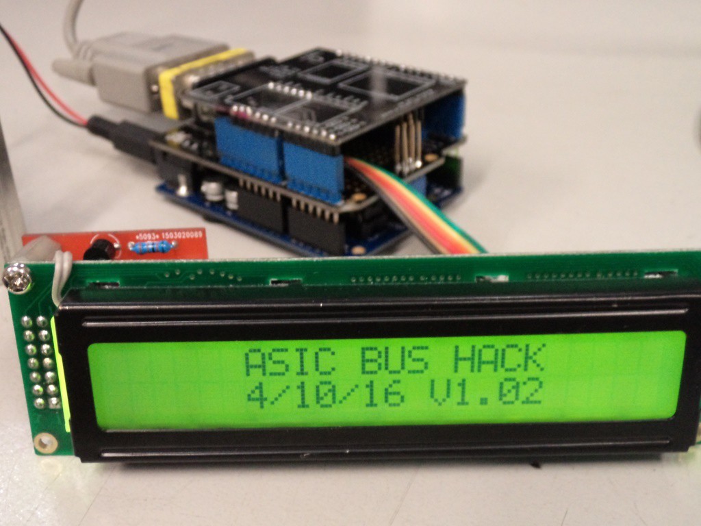
ASIC/2 HVAC PLC serial bus interface experiments.
The purpose of this project is to document my exploration of the communications bus used to exchange information between ASI Controls HVAC control equipment - particularly my analysis of the structure of the data packets used to transfer information between the devices.
Using the acquired knowledge of the packet structure, I have been able to construct and code an Arduino based device that can successfully send and receive data on the bus.
Using my knowledge of the internal data structures of the ASIC controllers, I can obtain and display temperature values and other data using this device.
System Description
The HVAC system being investigated is for a factory administration building. It is fairly basic and consists of 3 control components:
- ASIC/2-7040 “Configurable System Controller”
- ASIC/2-8540 “Configurable Unitary Controller”
- UnioOP - ePAD04 Human Machine Interface (HMI) panel.
The “ASIC/2” controllers are for I/O control and are made by ASI Controls.
ASIC produce programmable control equipment primarily for Heating, Ventilation and Air Conditioning (HVAC) applications.
The “UnioOP – ePAD04” HMI panel provides an operator control interface and is made by Exor.
These three hardware devices are linked by an RS-485 serial communication bus.
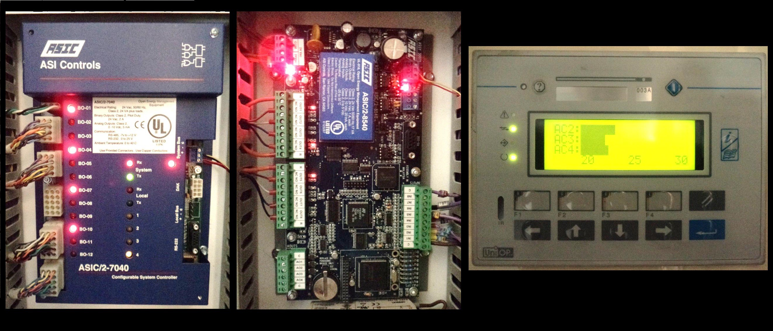
Above: ASIC/2-7040, ASIC/2-8540 and ePAD04 as installed.
Programming and configuration of the ASIC/2 controllers and ePAD HMI is performed using proprietary software packages.
For the ASIC/2 controllers, this package is “Visual Expert”
For the Exor HMI panel, this package is “Designer 6”.
I have access to a licenced copy of each of these software packages. I will NOT provide free copies of these software packages. Please do not ask!
Background and rationale
I am responsible for electrical and control system maintenance at the factory where this HVAC system is installed.
This project started with the idea of creating a display to show a temperature profile of the office over time by plotting the room temperature sensor data.While this is possible using the “Visual Expert” programming software, the function is intended primarily for commissioning and fault finding and is not a practical long term solution.
The common method would be to purchase, install and configure an additional HMI display panel or purchase a licence for specialised software from ASIC that allows a PC to be configured as such a display, however both these options are relatively expensive and I knew that I would certainly not get purchasing approval for such software or equipment for this trivial application.
My primary job function is understanding and maintaining the control systems of our industrial production equipment.I also enjoy making my own hardware (for non critical applications) and have some experience with micro controllers (particularly the Arduino platform) as well as general programming experience and electronics knowledge.I therefore decided to see if I could build my own interface.
My usual first step is to consult whatever technical documentation is available.
ASI Controls technical support model depends on the use of “Value Added Resellers” (VAR’s). For ANY and ALL enquiries regarding technical details of their equipment and software (beyond the most basic data sheets), ASI Controls inevitably refers to you to your local VAR.
I happen to live in a city of about two million people, of which exactly one is a ASI Controls VAR.This person has a business to run and (not surprisingly) is somewhat disinterested in providing free technical support.
ASI Controls has ALL technical documents and manuals locked away behind firewalls only accessible by VAR’s. This applies even if you have legitimately purchased licensed copies of the configuration software.
I choose to believe that the rationale for this is to prevent unauthorised tampering with building HVAC systems, however as an authorised maintainer of such a system and owner of a licensed copy of the configuration software purchased legitimately via my local VAR, I find this attitude somewhat irksome.
The initial documentation provided (grudgingly) with ASI’s “Visual Studio” provided very little detail on the data structures used by the system or the communication bus.
Through persistent “google foo” I have been able to obtain technical manuals which outline the data structures for the different software control “objects”.This was critical to understanding how to use my legitimately purchased and licensed software, not just for esoteric hijinks like decoding the data packet structure.
I cannot understand why ASI Controls made it so difficult to access this information.
Grabbing data from the bus.
This was actually pretty easy. The system in use on our site is configured such that an auxiliary RS-232 port on the 7040 module simply mirrors the activity on the RS-485 bus.
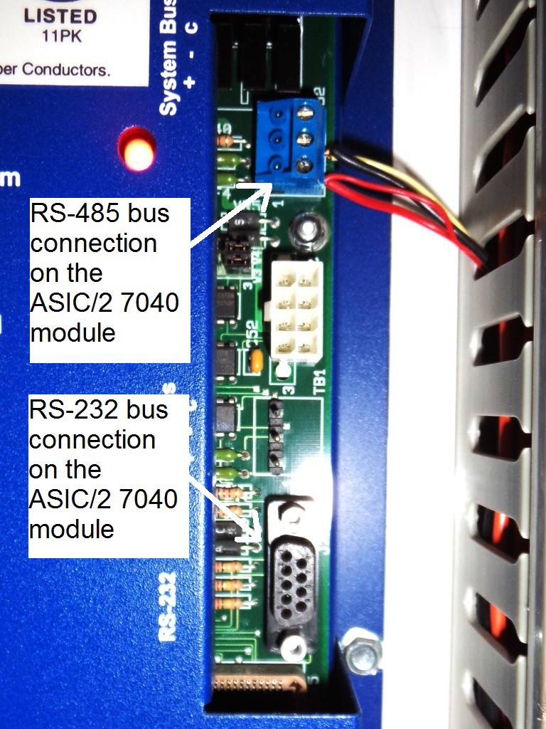
Above: location of the bus connections on the ASIC/2-7040 module.
his RS-232 port is primarily used for programming and monitoring the controllers with the “Visual Expert” software. By using “Free Serial Port Monitor 3.31” by HHD Software, I was able to easily capture data packets on the bus in hex format.
http://www.serial-port-monitor.com/
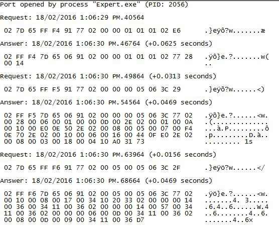
Above: Raw data as captured using the serial port monitor.
Each hex number represents 1 byte of data.Since I know the hardware address (node) of each controller from the “Visual Expert” application, I could immediately identify that each data packet contained a destination hardware address and an origin hardware address.
Understanding the remaining content of these messages requires some understanding of the way data is stored and manipulated in the ASIC/2 controllers.
ASIC/2 data structures.
The following is paraphrased from the ASIC/2 documentation:
The software control elements of the ASIC/2 are referred to as “Objects”. Objects perform a specific function and have a specific data structure associated with them. Objects include “Inputs” and “Outputs” for dealing with digital and analogue signals, “Clock” objects for time keeping. “Logic” objects for boolean operations and a host of other more specialised structures.
Each object type can be used multiple times, with each use called an “Instance”.For an Input or Output object, the Instance will correspond to a physical input or output.
Each Object Instance consists of many bytes of data. This data is partitioned into “Attributes”.For example, the first two bytes of an Input Object are the Attribute “Present Value”.
An Attribute may be further divided, so to find the state of a single status bit (for example), you must “Select” the required bit.
Together Object/Attribute/Instance/Select provides a “Handle” that is a unique address for every data point in the system.
Data telegraph structure: Query.
A typical QUERY telegraph on the data bus is 15 bytes long. Below is an example of a request from the ePAD HMI screen for the present value of an analogue input on the 7040 controller.
02 7D 65 FE F2 91 77 02 05 03 00 01 01 02 EA
I have started the numbering from zero to simplify reference to the code:
Byte 0: Start of message signal. Always 0x02
Byte 1: Destination node (the 7040 controller) address HI byte
Byte 2: Destination node address LO byte
Destination node address is always a 16 bit word. If the system uses “token passing”, the node address will be between 32001 and 32255. Our system does not, however the address is still in that range. 0x7D65 = 32101. Depending on the installation configuration, any addresses in the range 00001 to 65535 “not divisible by 256” seem to be possible. The value 0x5AFF (23295) indicates a “global” message.
Byte 3: Origin node (the ePAD display) address HI byte
Byte 4: Origin node address LO byte
In this case the origin node address is the ePAD panel. 0xFEF2 = 65266.
Byte 5: Function code.
I have not been able to locate a function code list in any of the documentation I’ve found. I assume 0x91 is something like “read value”.
Byte 6: Unknown. Always 0x77 in this sort of data query telegraph.
The value 0x77 always appears after the function code in a query and before data in response. Probably an “end of header” or “start of data” signal?
Byte 7: Delimiter? “Start of handle” signal? Always 0x02.
Byte 8: Handle - “Object”
Values consistent with the type values as defined in the Visual Expert configuration software. E.g. 0x05 is an Input object, 0x03 is an Output object, etc.
Byte 9: Handle - “Instance”
For inputs and Outputs, values consistent with the physical hardware address as defined in the Visual Expert configuration software.
Byte 10: Handle – “Attribute”
Byte 11: Handle – “Select”
Byte 12: Unknown.
Byte 13: Delimiter? “End of handle” signal? Always 0x02.
Byte 14: Check sum.
The check sum is simply the lowest byte of a simple addition of all the other query message bytes
Data telegraph structure: Response.
A RESPONSE telegraph on the data bus has a length that depends on what the query was. The response for a query like the one above on a single input or output value is always 18 bytes long. It is this type of response that is examined below.
02 FE F2 7D 65 06 91 02 05 03 00 01 01 02 77 AB 08 A3
Again, I have started the numbering from zero to simplify reference to the code:
Byte 0: Start of message signal. Always 0x02
Byte 1: Destination node (the ePAD display) address HI byte
Byte 2: Destination node address LO byte
Byte 4: Origin node (the 7040 controller) address HI byte
Byte 5: Origin node address LO byte
Note that since this is a response, the destination and origin values are simply the inverse of the request message.
Byte 6: Unknown. Seems to be always 0x06 for this type of response telegraph.
Perhaps an acknowledge code indicating that the message is a response?
Byte 6: Echo of Function code in byte 6 of the query.
Byte 7: Delimiter? “Start of handle” signal? Always 0x02.
Byte 8: Handle - “Object”. Echo of byte 9 of query.
Byte 9: Handle - “Instance”. Echo of byte 10 of query.
Byte 10: Handle – “Attribute”. Echo of byte 11 of query.
Byte 11: Handle – “Select”. Echo of byte 12 of query.
Byte 12: Unknown. Echo of byte 13 of query.
Byte 13: Delimiter? “End of handle” signal?
0x02 if data is returned. 0x00 if the handle is not defined in the controller..
Byte 15: Unknown. Always 0x77 in this sort of data response telegraph.
The value 0x77 always appears after the function code in a query and before data in response. Probably an “end of header” or “start of data” signal?
Byte 16: First data byte (“LO” byte).
Byte 17: Second data byte (“HI” byte).
The Visual Expert manual states that Attribute 0 of an INPUT object is “Present Value” and has the type “signed word”, but this type is a little misleading and depends on the data being represented.The data being represented is configured in the Visual Expert configuration software.
- For a binary type Input, 0xFFFF is ON and 0x0000 is OFF.
- For an analogue type Input, the 10 bit raw value from the physical input is stored, presumably with the MSB of the HI byte being the sign bit and the remaining 5 bits of the HI byte set to 0.
- If a “conversion type” is set for the analogue Input in the Visual Expert software to correct the raw value according to the type of sensor used, MSB of the HI data byte is again the sign bit (not confirmed) and presumably all the remaining HI and LO bits encode the data, giving a possible range of +/-32767. I have confirmed that on our system the base 10 value encoded in these bytes can be simply divided by 100 to give the present temperature value in Centigrade to 2 decimal places. It may be possible for temperature values up to a ridiculous 327.67oC ( LO = 0xFF, HI = 0x7F) and below absolute zero (- 327.67oC : LO = 0xFF, HI = 0xFF) to be encoded by this method. However a lookup table is used for the conversion so I suspect that there are upper and lower limits based on the practical range for the type of sensor selected.
The Visual Expert manual states that Attribute 0 of a DIGITAL OUTPUT object is “Present Value” of type “word”, but this is again a little misleading. The data is encoded in only the “LO” byte: 0x0001 is ON and 0x0000 is OFF.
The Visual Expert manual states that Attribute 0 of an ANALOGUE OUTPUT object is also “Present Value” of type “word”, but again this is a little misleading. The data is encoded in only the first “LO” byte as a value between 0 (0x0000) and 255 (0x00FF).This drives an actual voltage value at the output between 0 and 10V.
Byte 18: Check sum.
Again, this is the lowest byte of a simple addition of all the previous message bytes.
Bus Hacking hardware
Very little hardware was required for the initial proof of concept:
- An Arduino Uno. https://www.arduino.cc/
- An RS232 “shield” from Seeed Studios. http://wiki.seeedstudio.com/wiki/RS232_Shield
- A D9 null modem cable and gender changer.
Arduino is a well-known open source microprocessor development board and Integrated Programming Environment (IDE) aimed at the hobbyist but certainly capable of integration into sophisticated control equipment. The Arduino constellation includes a vast amount of user contributed code and an equally vast ecosystem of related auxiliary circuit modules (“shields”).
The RS232shield utilises a MAX232 IC to convert between the TTL Arduino signals and the significantly higher and lower RS232 voltages. I do not intend to discuss the technical aspects of RS232 here but suffice to say, it is a really bad idea to try to connect an Arduino to an RS232 bus without this type of voltage level conversion.
The shield also allows the TX and RX signals to be connected to any of the Arduino digital pins, thus making it possible to use the “Software Serial” library.The leaves the Arduino UART pins free for standard USB/Serial programming uploads and communication.
The shield is supplied with a female D9 connector and configured as a DCE (data carrier equipment) device. Since the ASIC controller is also a DCE device, the two are not directly pin compatible. Thus, a null modem cable and gender changers are required, so that the Arduino acts as a DTE (data terminal equipment) device like a laptop running a terminal emulator (e.g. puTTY.)
Bus Hacking Code
The code was written using the standard Arduino libraries.I’m not a programmer by trade so I offer the following Randall Munroe masterpiece by way of humble apology:

Three iterations of the Arduino code are available on GitHub:
https://github.com/MildLeeInterested/ASIC_hacks
- Version 1- (ASIC_readOnly.ino) : Monitors the bus and identifies response telegraphs that contain the “present value” data for selected analogue inputs, extracts that data and displays it on the serial monitor. It does NOT make the request for the data. Instead, it intercepts responses intended for the HMI panel. This was good enough for a first attempt.
- Version 2 – (ASIC_writeAndRead.ino): Expands upon this base to request specific data. It requests “present value” data for selected analogue inputs, extracts that data from the response and displays it on the serial monitor.
- Version 3 – (ASIC_StandAlone.ino):A modified version that displays the values on a standard 24x2 character LCD display, thus making a standalone device that does not require a laptop to function.
I do not intend to document the use of this LCD here, as this information is easily obtained elsewhere. Note, however, that the circuit makes use of a shift register to reduce the number of pins required to run the LCD.The “LiquidCrystal595” library by Rowan Simms is used to drive this hardware.
https://github.com/haiphamngoc/LiquidCrystal595
Conclusion
Reverse engineering the ASIC control bus protocol to this point has been relatively simple.
A great deal remains to be done in order to identify the function of the various control characters included in each message. Given the simplicity of the protocol, I remain extremely surprised at the attitude of ASI Controls in not making the information available upon request.
The next step will be to implement the original goal: display a plot of temperature over time on a suitable display.
Update
The completed project has resulted in a simple display showing comparative temperatures in the air-conditioned administration building, compared to the non-air-conditioned factory.
The display is in oC and this is self-evident in context, as “the old scale” is very rarely used in Australia. For maximum impact, the column colour depends on the temperature displayed.
This primitive display is an effective “social hack” that has substantially reduced the frequency of complaints from admin staff about the temperature of the office!
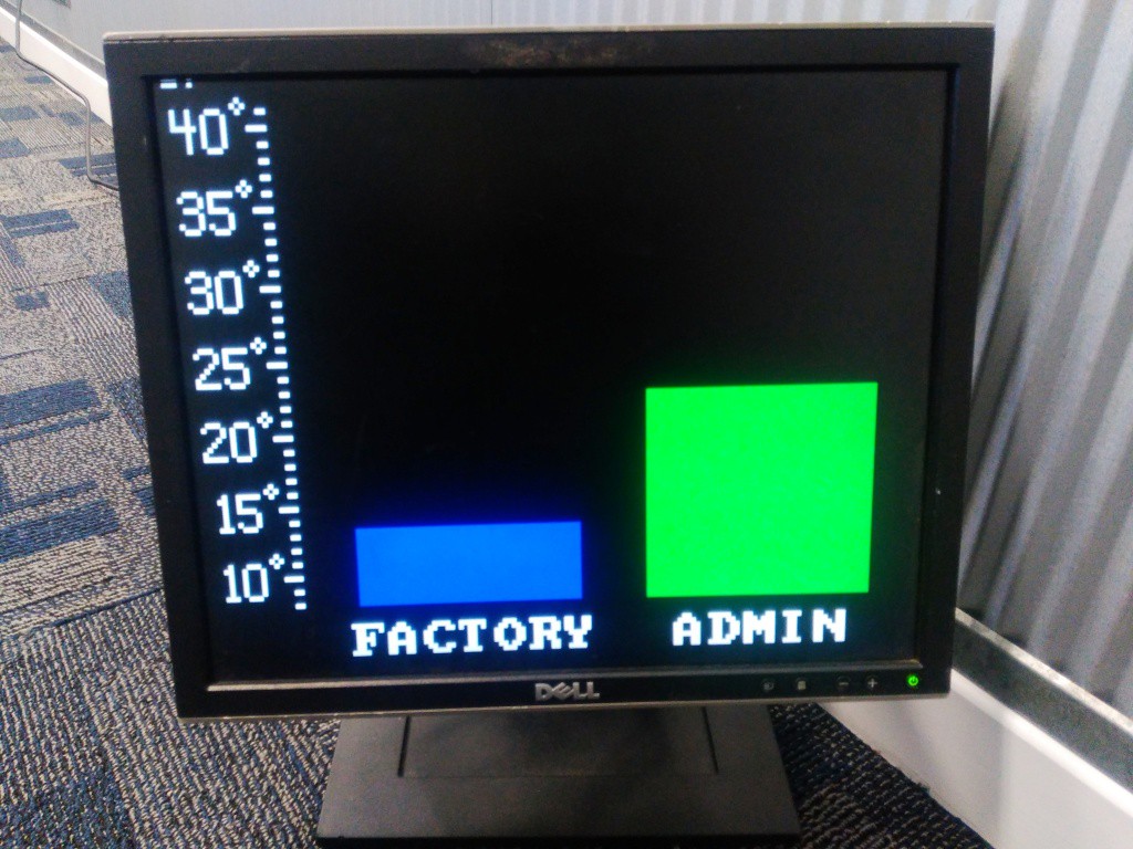
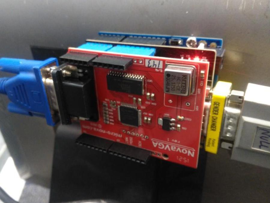
Additional components are:
• A discarded VGA monitor
• A specialised VGA “shield” from microNova
https://www.micro-nova.com/novavga
The “NovaVGA” shield is a low cost FPGA based device that comes with a simple to use Arduino code library and examples. The resolution is a chunky 160x120 pixels, but this is adequate for the purpose.
The entire package is fixed to the back of the monitor and powered by the integral USB hub on the monitor so that the only external cables are the 240V supply to the monitor and the null modem cable.
Update 2
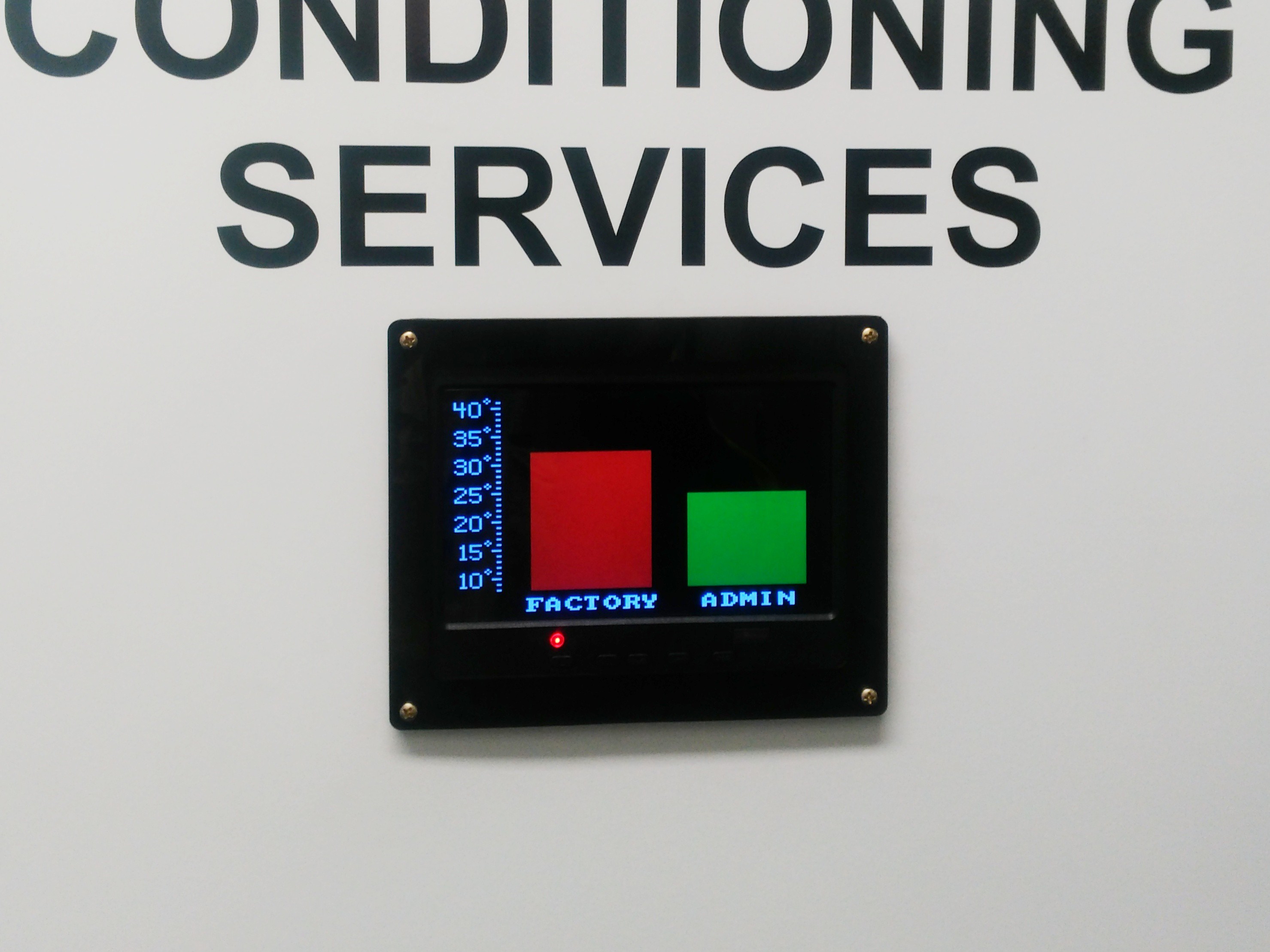
Display integrated into door of HVAC control cupboard using a small VGA monitor
 Mild Lee Interested