 Ted Yapo
I designed a 32x32mm breakout PCB for the A111 sensor today. The datasheet says you need a solid ground plane on the top layer. I did the best I could using the OSH Park 2-layer rules. The reference PCB sold as a development module has a really unbroken ground plane - they must be using via-in-pad, which isn't an option here.
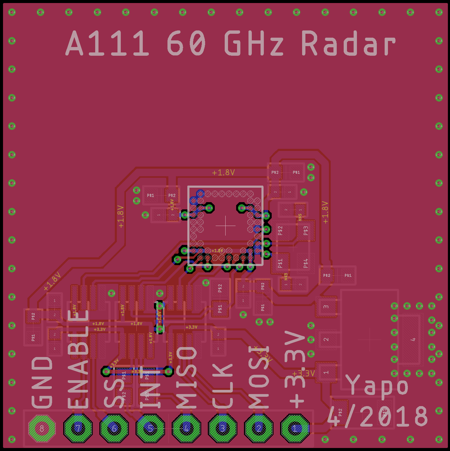
The datasheet states that the plane is required as a reflector for the antennas. I suspect this plane shields the signal traces from picking up the 60GHz signal, too. 60GHz has a wavelength of 5mm in air, so a resonant 1/4-wave antenna is only 1.25 mm long. That's shorter than the length of a via (1.6mm) on this board!
There are a few traces on the top side. They all look like great antennas at 60 GHz, but I'm hoping I can get away with it. Even the 2mm spacing between stitching vias at the board edge is way too huge for 60 GHz - they're 2/5 of a wavelength apart. They're really there for the lower-frequency signals on the board.
There are also three places where I had to cheat on design rules - 6/6 isn't small enough to bring one of the traces out of the BGA. I ended up with a short segment violating the width and spacing on both sides, but I'm hoping that I'll still get a workable board.
Only the radar module itself is on the top; the rest of the components are on the bottom.
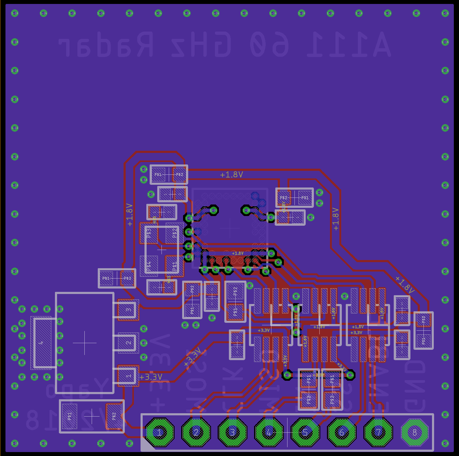
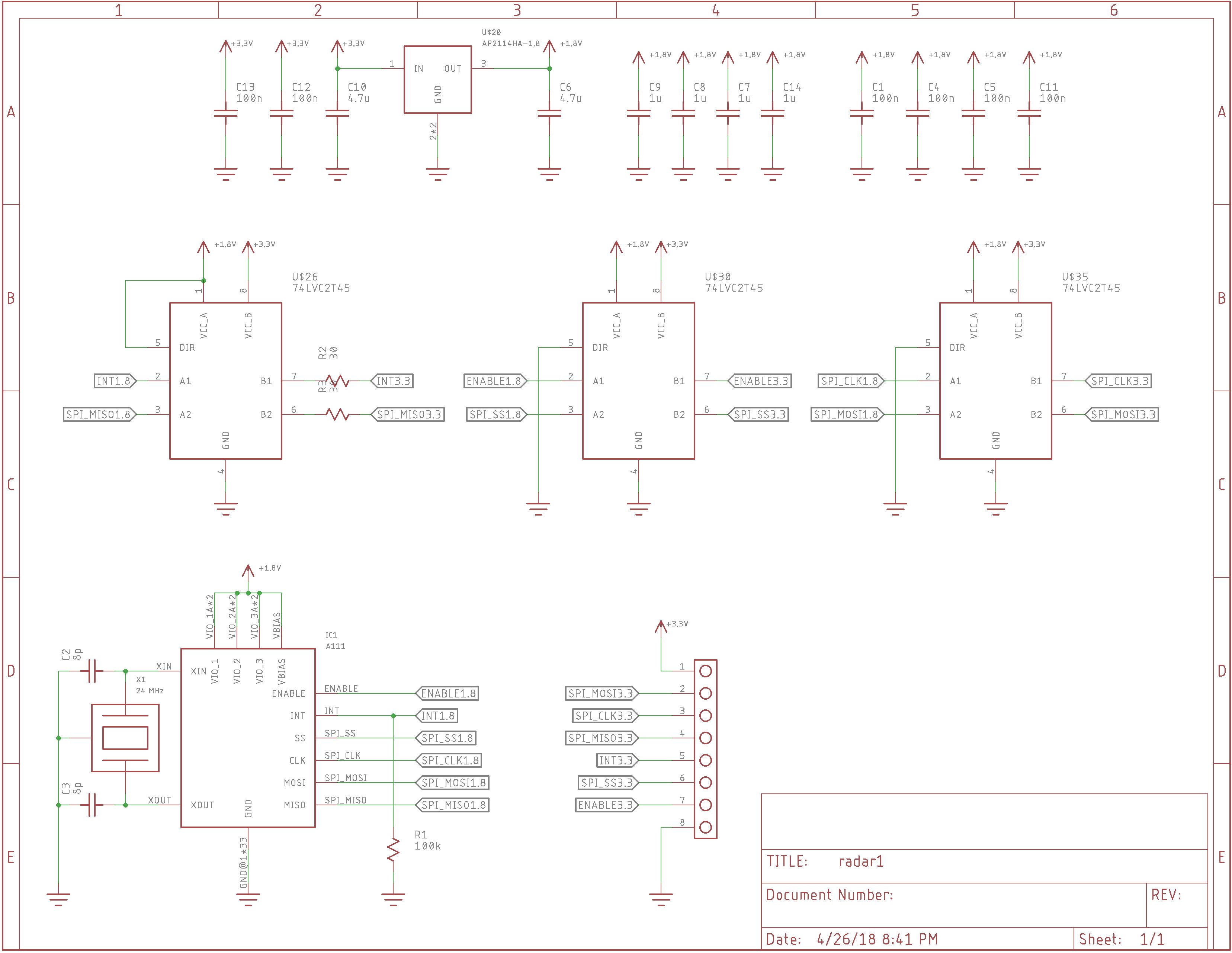
The circuit is a basic breakout board. A 1.8V regulator supplies power to the A111, while 3x 74LVC2T45's translate the digital interface from 1.8 to external logic levels between 1.8-5V for maximum flexibility. I'll almost certainly just use it at 3.3V, but it's nice to have the option so early on.
This board really is just a quick test so I can get some mileage on the part, find any issues quickly, and start playing with software.
For the final sensor module, it looks like it makes sense to integrate a cheap MCU on the board, but the details have yet to be worked out.
Now I wait for parts and PCB to arrive.
Discussions
Become a Hackaday.io Member
Create an account to leave a comment. Already have an account? Log In.
I wonder if the thickness of the PCB will have an impact here too. Do you plan to use the standard 1.6mm?
Are you sure? yes | no
The first proto is on 1.6mm mainly because I can have it in my hand in about a week.
If the top plane were really continuous, the circuit on top couldn't tell how thick the PCB was. One of the speakers at ESC noted that there's around 200dB loss through a solid copper ground plane. Since there are some holes, it may make a difference, but I have no idea how much. Hopefully, the chip itself is designed right - there's little I can really control about 60GHz signals on a 6/6 FR4 PCB.
Are you sure? yes | no