To generate the power sequence timing signals, some sort of clock is required. Since I've limited myself to parts-on-hand, I'll use a 1 MHz oscillator. Now, I can't get a very accurate 60Hz signal out of that for the Line Time Clock (LTC), but I can get kind of close. I could run the LTC at 50Hz but I'm going with 60... I could let the M8047 generate the LTC signal, but if I need to replace it somewhere down the line for 22-bit address support, then I'll need another LTC source. So I might as well generate it on my board.
Approximating 60Hz
1 MHz is 60Hz * 16666.666... Like I said, I can't generate that exactly. But how about dividing by 16667? That would be within 20ppm. However, we want the result to have a 50% duty cycle and that will be hard when dividing by an odd number. So how about 16666? That's within 40ppm. But I don't have the chips to do it. If I had four 74LS163 (4-bit presettable) counters I could do it, but I only have two. Other chips I have on hand are a 74S169 (4-bit presettable up/down counter) and a 74LS390 (dual 4-bit decade counter). Using those, I can divide by 16660, and that'll generate 60.024Hz which is off by about 400ppm. Not good enough for a time-of-day clock. Oh well, close enough for my purposes.
Generating the Delays
OK, so let's look at the timing diagram again:
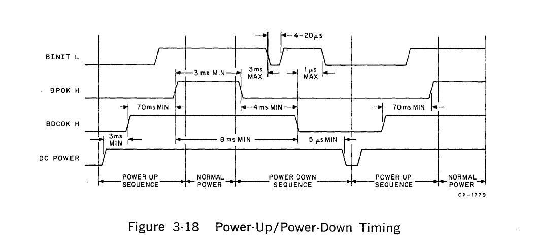
After the +5V supply stabilizes, we have to wait at least 3msec before asserting BDCOK. Then we have to wait at least 70msec before asserting BPOK. A shift register clocked off our 60Hz signal can provide these delays.
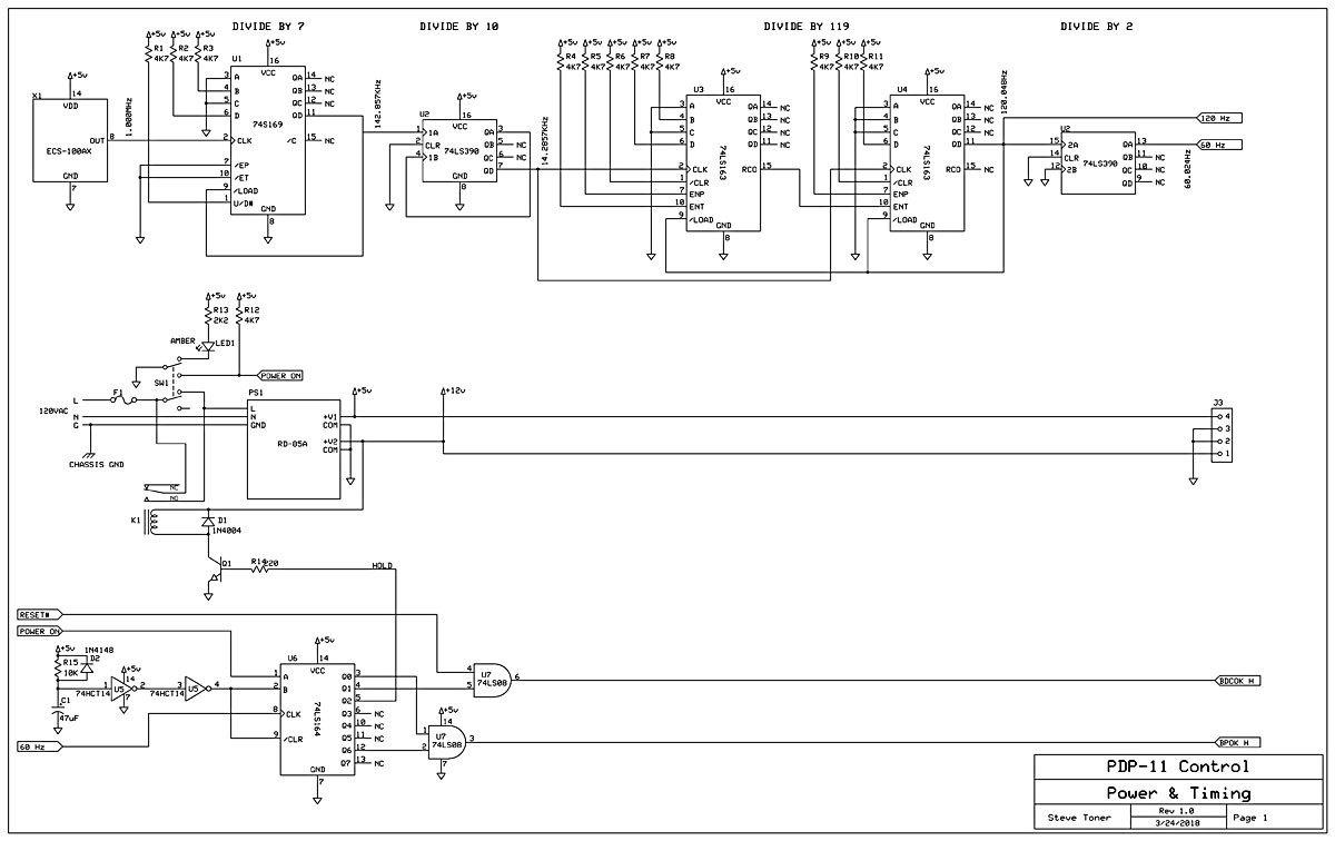
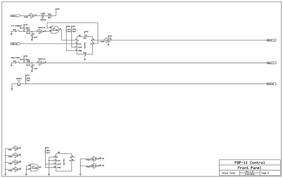
Schematics
Verifying the Timing
Using the oscilloscope of the HP 1631D Logic Analyzer, we can view the signal timing:
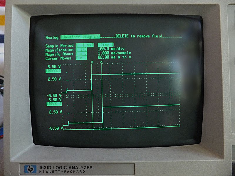
The scope is triggering on the +5V power supply when it reaches 4.5V. The x and o markers show approximately 82 msec between BDCOK and BPOK, which is more than the required 70 msec. From +5V supply at 4.5V to BDCOK is around 250msec, which is well over the required 3 msec, even if we allow some time for the supply voltage to stabilize at 5.0V.
Discussions
Become a Hackaday.io Member
Create an account to leave a comment. Already have an account? Log In.