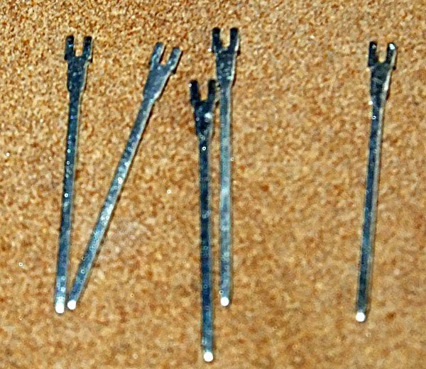
OK, while I'm waiting on parts to get the M8047 working, let's go back and look at the control & timing board. Again, the goal here was to use parts I had on hand and that rule applied to the PCB and sockets as well as the chips. I had a cut-off piece of a prototyping board, about 4"x4". It has 2 holes-per-pad. I also had a few (35 year) old wire wrap sockets, so wire wrap seemed like the way to implement this board. I didn't have enough wire wrap sockets for all the parts, but I did have a whole bunch of wire wrap pins that can be soldered into the second hole next to a regular socket's pin and provide a means to wrap to that pin on the IC.
OK, so with parts from AVX, Bourns, ECS, Fairchild, Motorola, National Semiconductor, Signetics, Texas Instruments and I-don't-know-who-all, here is the board:
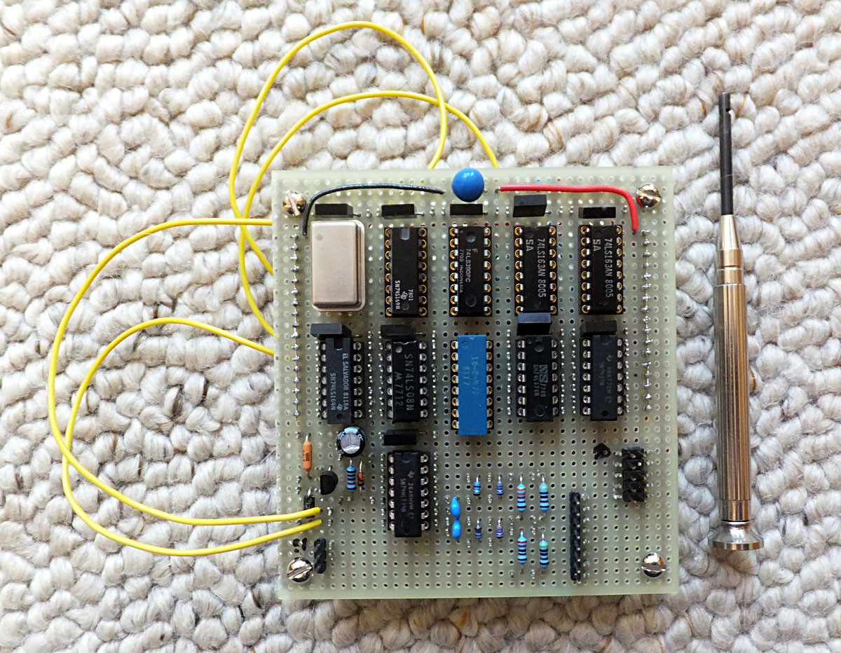
The top row has the nice gold-plated wire wrap sockets, and the rest of the sockets are of the solder tail variety, as you can see. The tool on the right is a manual wire wrapping (and unwrapping!) tool, also on the order of 35-40 years old. I think I got it at Radio Shack back in the day... Also, note the power and ground buses on the upper half of the right & left sides of the board. That blue "chip" in the middle is actually 15 resistors (pin 16 is common), which are used as pullups.
The bottom side of the board:
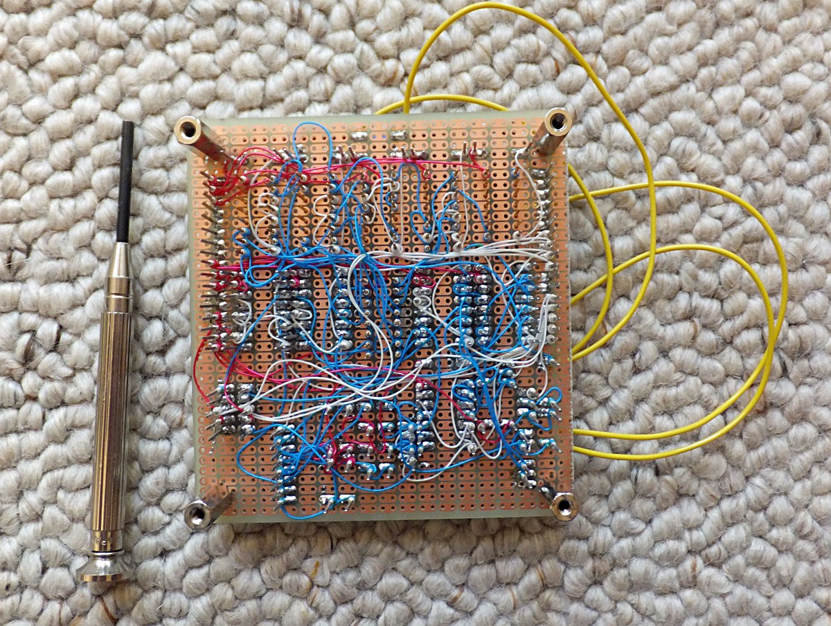
I had some old red & white wire, so used red for +5V and white for GND. The blue wire is of more recent vintage.
Discussions
Become a Hackaday.io Member
Create an account to leave a comment. Already have an account? Log In.