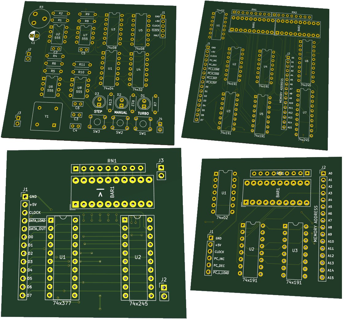
After a bit of a pause I've picked up where I left.
Now that the entire computer is working in Logisim, I've decided to try to bring it to life and solder the whole thing together.
I'm going for a modular approach for which each of the computer's components (e.g. register, clock, stack pointer) is built as a separate PCB.
The inputs & outputs (control lines, address lines, data lines) for each module are exposed using male header pins. This allows me to easily test each module individually.
Once all the modules are in working order, they will be connected on each other on top of one large PCB with header sockets.
At least that is the plan!
So far I've finished the Clock, Register(s), Progam Counter and Stack Point modules (although they are stil untested).

 Ruud van Falier
Discussions
Become a Hackaday.io Member
Create an account to leave a comment. Already have an account? Log In.