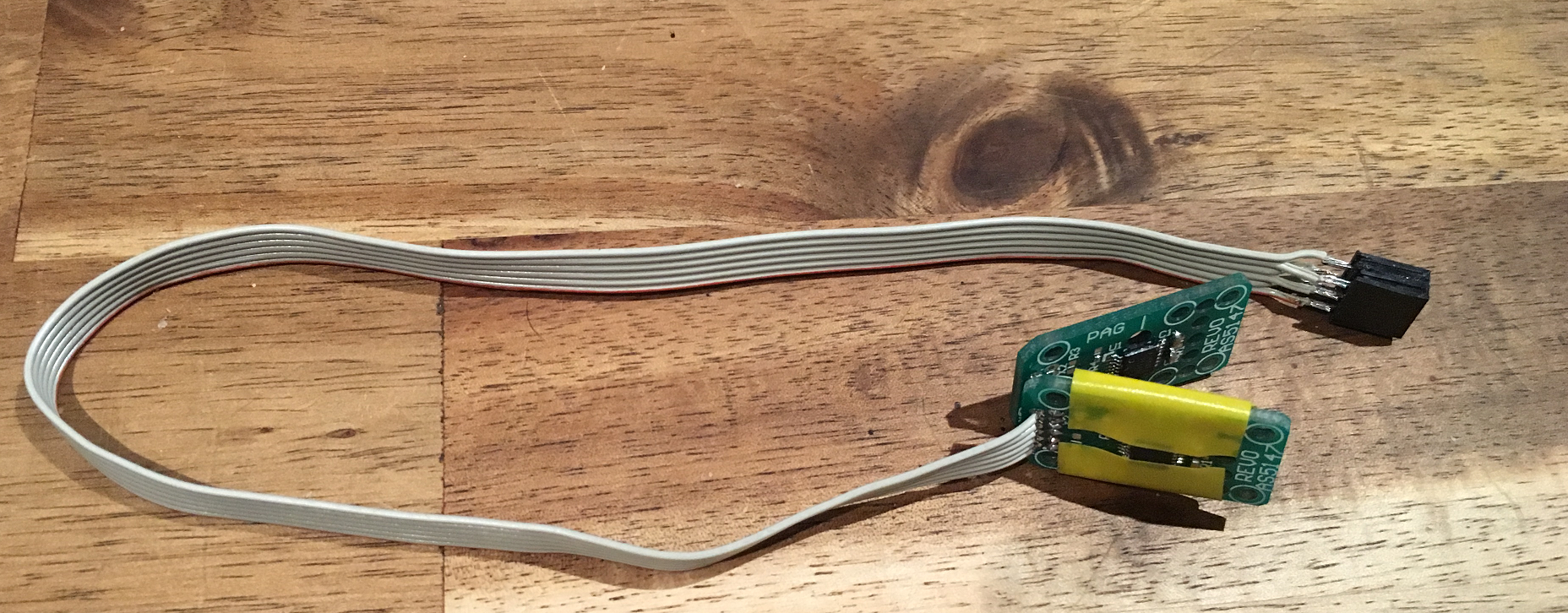
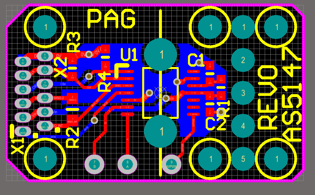
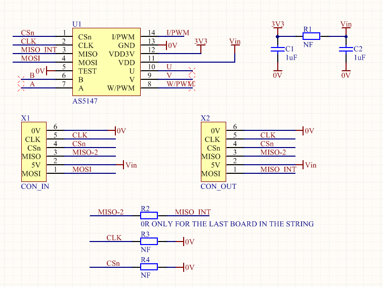
The position sensor board uses the AS5147 is a 14-bit Magnetic Encoders

One for is used for the motor electrical position/angle. One is used for the joint position/angle. The are connected via daisy chain on SPI communication with 2x 16bit clocking. There is a piece of Silicon Steel between the two sensors boards to prevent cross flux of diametric magnets.
The technical information for the system:-
- 14500RPM (240 REV/sec)
- Multistar Elite 5008 motor maximum speed 7000 RPM
- 7 Pole pairs
- 10kHz sample rate (85 samples per revolution at full RPM)
- 12 samples for electrical rotation at full RPM
- DAEC™ dynamic angle error compensation
This basically means that they are quite suitable for this application.


The Schematic and PCB has been uploaded to the "file page".
 Paul Gould
Discussions
Become a Hackaday.io Member
Create an account to leave a comment. Already have an account? Log In.